SEAT BELT WARNING SYSTEM(w/ Occupant Classification System) TERMINALS OF ECU
-
CHECK COMBINATION METER ASSEMBLY
-
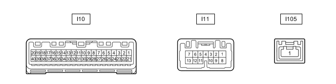
Disconnect the I10 combination meter assembly connector.
-
Measure the resistance and voltage according to the value(s) in the table below.
Tester Connection Wiring Color Terminal Description Condition Specified Condition I10-21 (IG+) - Body ground B - Body ground IG power supply Engine switch on (IG) → off 11 to 14 V → Below 1 V I10-22 (B) - Body ground Y - Body ground Battery power supply Always 11 to 14 V I10-31 (ES) - Body ground W-B - Body ground Ground Always Below 1 Ω
-
-
CHECK AIRBAG ECU ASSEMBLY
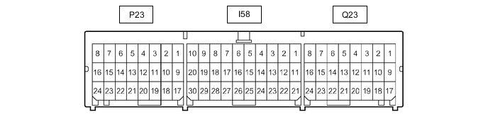
Terminal No. Terminal Symbol Destination Q23-15 LBE+ Front seat inner belt assembly LH Q23-23 LBE- Front seat inner belt assembly LH P23-9 FSR+ Occupant detection ECU P23-17 FSR- Occupant detection ECU -
CHECK OCCUPANT DETECTION ECU

Tech Tips
Since the occupant detection ECU uses waterproof connectors, the voltage and waveform cannot be inspected directly. Standard voltage readings and waveforms are indicated for reference only.
Terminal No. (Symbol) Wiring Color Terminal Description Condition Specified Condition f14-1 (SVC1) - f14-5 (SGD1) R - G Front occupant classification sensor LH power supply Engine switch on (IG) 4.9 to 5.1 V f14-2 (SVC3) - f14-6 (SGD3) GR - W Rear occupant classification sensor LH power supply Engine switch on (IG) 4.9 to 5.1 V f14-3 (SIG1) - f14-5 (SGD1) P - G Front occupant classification sensor LH signal Engine switch on (IG) Pulse generation f14-4 (SIG3) - f14-6 (SGD3) SB - W Rear occupant classification sensor LH signal Engine switch on (IG) Pulse generation f14-5 (SGD1) - f15-3 (GND) G - W-B Front occupant classification sensor LH ground Always Below 1 V f14-6 (SGD3) - f15-3 (GND) W - W-B Rear occupant classification sensor LH ground Always Below 1 V f15-1 (+B) - f15-3 (GND) W - W-B Power source (+B) Always 11 to 14 V f15-2 (DIA) GR Diagnosis (DLC3) -* -* f15-3 (GND) - Body ground W-B - Body ground Ground Always Below 1 V f15-4 (FSR-) - f15-3 (GND) LG - W-B Airbag ECU assembly communication signal Always Below 1 V f15-5 (BGND) - f15-3 (GND) P - W-B Front Passenger side buckle switch ground Always Below 1 V f15-6 (IG2) - f15-3 (GND) B - W-B Power source (IG) Engine switch on (IG) 11 to 14 V f15-7 (FSR+) - f15-4 (FSR-) L - LG Airbag ECU assembly communication signal Engine switch on (IG) Pulse generation f15-8 (BSW) - f15-5 (BGND) G - P Front Passenger side buckle switch signal Always Pulse generation
-
*: As this is a line that is connected to other systems, voltage changes according to the systems that are connected.
-