SEAT HEATER SYSTEM, Diagnostic DTC:B14C0
| DTC Code | DTC Name |
|---|---|
| B14C0 | Front Right Seat Heat Sensor Circuit |
DESCRIPTION
Output to the front seat cushion heater temperature sensor stops if one of the following occurs: 1) the temperature sensor is open or shorted; or 2) the temperature sensor is damaged and its output value does not change.
| DTC No. | Detection Item | DTC Detection Condition | Trouble Area |
|---|---|---|---|
| B14C0 | Front Right Seat Heat Sensor Circuit | Seat heater temperature sensor malfunction |
|
-
*1: for L-Sport Seat Type
-
*2: for F-Sport Seat Type
WIRING DIAGRAM
-
for L-Sport Seat Type
-
for LHD:
-
for Power Seat:
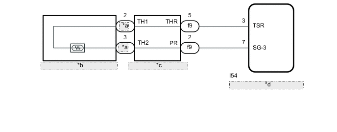
*a SHR *b Separate Type Front Seat Cushion Cover RH *c Seat Heater Control Sub-assembly RH *d Air Conditioning Amplifier Assembly -
for Manual Seat:

*a SHR *b Separate Type Front Seat Cushion Cover RH *c Seat Heater Control Sub-assembly RH *d Air Conditioning Amplifier Assembly
-
-
for RHD:
-
for Power Seat:
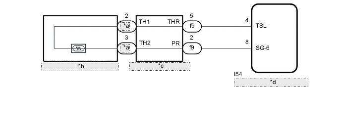
*a SHR *b Separate Type Front Seat Cushion Cover RH *c Seat Heater Control Sub-assembly RH *d Air Conditioning Amplifier Assembly -
for Manual Seat:
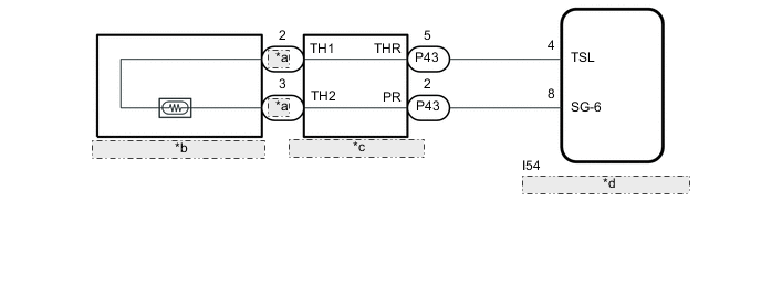
*a SHR *b Separate Type Front Seat Cushion Cover RH *c Seat Heater Control Sub-assembly RH *d Air Conditioning Amplifier Assembly
-
-
-
for F-Sport Seat Type
-
for LHD:
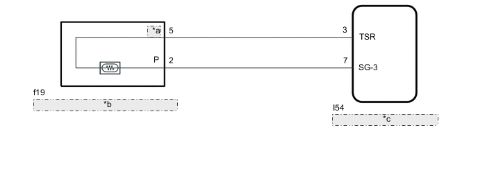
*a TH *b Front Seat Cushion Pad with Cover RH *c Air Conditioning Amplifier Assembly -
for RHD:
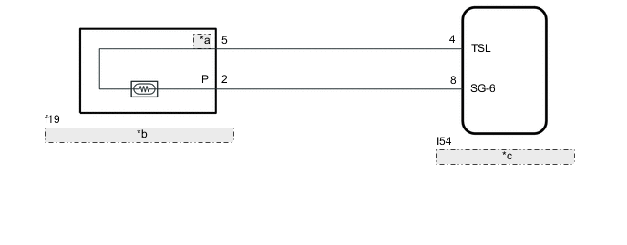
*a TH *b Front Seat Cushion Pad with Cover RH *c Air Conditioning Amplifier Assembly
-
CAUTION / NOTICE / HINT
Note
-
If the battery voltage is low, the seat heater system may not operate. When "High Power Consumption / Partial Limit On AC/Heater Operation" is displayed on the multi-information display in the combination meter assembly, inspect the battery, referring to On-vehicle Inspection for the charging system.
Tech Tips
If the battery voltage is low, "Operation Limitation Control History Count (Level 1)" and "Operation Limitation Control History Count (Level 2) is counted.
-
for 8AR-FTS: Click here
-
for 3ZR-FAE: Click here
-
If the battery voltage is low, the seat heater system may not operate. Refer to Data List for the power steering system.
-
for Manual Tilt and Manual Telescopic Steering Column: Click here
-
for Power Tilt and Power Telescopic Steering Column: Click here
PROCEDURE
-
CLEAR DTC
-
Clear the DTCs.
Body Electrical > Air Conditioner > Clear DTCsResult Proceed to NEXT
NEXT 
-
-
CHECK FOR DTC
-
Check for DTCs.
Body Electrical > Air Conditioner > Trouble CodesOK DTC B14C0 is not output. Result Proceed to OK NG
OK 
USE SIMULATION METHOD TO CHECK Click here
NG
-
-
READ VALUE USING GTS (FR Seat Heater Temperature)
-
Connect the GTS to the DLC3.
-
Turn the engine switch on (IG).
-
Turn the GTS on.
-
Enter the following menus: Body Electrical / Air Conditioner / Data List.
-
Read the Data List according to the display on the GTS.
Body Electrical > Air Conditioner > Data ListTester Display Measurement Item Range Normal Condition Diagnostic Note FR Seat Heater Temperature Front seat RH heater temperature -29.7°C to 59.55°C Within range from 32 to 43°C (89 to 109°F) Front seat heater is on
Body Electrical > Air Conditioner > Data ListTester Display FR Seat Heater Temperature OK On the GTS screen, the seat heater temperature is as specified in the normal condition column. Result Result Proceed to OK A NG (for L-Sports Seat Type) B NG (for F-Sports Seat Type) C
A
REPLACE AIR CONDITIONING AMPLIFIER ASSEMBLY Click here
C 
INSPECT FRONT SEAT CUSHION PAD WITH COVER RH Click here
B
-
-
INSPECT SEPARATE TYPE FRONT SEAT CUSHION COVER RH
-
Remove the separate type front seat cushion cover RH.
-
for Manual Seat: Click here
-
for Power Seat: Click here
-
-
Inspect the separate type front seat cushion cover RH.
-
for Manual Seat: Click here
-
for Power Seat: Click here
Result Proceed to OK NG -
NG
REPLACE SEPARATE TYPE FRONT SEAT CUSHION COVER RH for Manual Seat: Click here for Power Seat: Click here
OK
-
-
INSPECT SEAT HEATER CONTROL SUB-ASSEMBLY RH
-
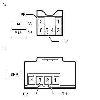
*A for Power Seat *B for Manual Seat *a Seat Heater Control Sub-assembly RH
(to Air Conditioning Amplifier Assembly)
*b Seat Heater Control Sub-assembly RH
(to Separate Type Front Seat Cushion Cover RH)
Disconnect the f9*1 or P43*2 and SHR seat heater control sub-assembly RH connectors.
-
*1: for Power Seat
-
*2: for Manual Seat
-
-
Measure the resistance according to the value(s) in the table below.
Standard Resistance for Power Seat Tester Connection Condition Specified Condition f9-5 (THR) - SHR-2 (TH1) Always Below 1 Ω f9-5 (THR) or SHR-2 (TH1) - Body ground Always 10 kΩ or higher f9-2 (PR) - SHR-3 (TH2) Always Below 1 Ω f9-2 (PR) or SHR-3 (TH2) - Body ground Always 10 kΩ or higher for Manual Seat Tester Connection Condition Specified Condition P43-5 (THR) - SHR-2 (TH1) Always Below 1 Ω P43-5 (THR) or SHR-2 (TH1) - Body ground Always 10 kΩ or higher P43-2 (PR) - SHR-3 (TH2) Always Below 1 Ω P43-2 (PR) or SHR-3 (TH2) - Body ground Always 10 kΩ or higher Result Proceed to OK NG
NG
REPLACE SEAT HEATER CONTROL SUB-ASSEMBLY RH for Manual Seat: Click here for Power Seat: Click here
OK
-
-
CHECK HARNESS AND CONNECTOR (AIR CONDITIONING AMPLIFIER ASSEMBLY - SEAT HEATER CONTROL SUB-ASSEMBLY RH)
-
Disconnect the I54 air conditioning amplifier assembly connector.
-
Disconnect the f9*1 or P43*2 seat heater control sub-assembly RH connector.
-
*1: for Power Seat
-
*2: for Manual Seat
-
-
Measure the resistance according to the value(s) in the table below.
Standard Resistance for LHD (for Power Seat) Tester Connection Condition Specified Condition I54-3 (TSR) - f9-5 (THR) Always Below 1 Ω I54-3 (TSR) or f9-5 (THR) - Body ground Always 10 kΩ or higher I54-7 (SG-3) - f9-2 (PR) Always Below 1 Ω I54-7 (SG-3) or f9-2 (PR) - Body ground Always 10 kΩ or higher for LHD (for Manual Seat) Tester Connection Condition Specified Condition I54-3 (TSR) - P43-5 (THR) Always Below 1 Ω I54-3 (TSR) or P43-5 (THR) - Body ground Always 10 kΩ or higher I54-7 (SG-3) - P43-2 (PR) Always Below 1 Ω I54-7 (SG-3) or P43-2 (PR) - Body ground Always 10 kΩ or higher for RHD (for Power Seat) Tester Connection Condition Specified Condition I54-4 (TSL) - f9-5 (THR) Always Below 1 Ω I54-4 (TSL) or f9-5 (THR) - Body ground Always 10 kΩ or higher I54-8 (SG-6) - f9-2 (PR) Always Below 1 Ω I54-8 (SG-6) or f9-2 (PR) - Body ground Always 10 kΩ or higher for RHD (for Manual Seat) Tester Connection Condition Specified Condition I54-4 (TSL) - P43-5 (THR) Always Below 1 Ω I54-4 (TSL) or P43-5 (THR) - Body ground Always 10 kΩ or higher I54-8 (SG-6) - P43-2 (PR) Always Below 1 Ω I54-8 (SG-6) or P43-2 (PR) - Body ground Always 10 kΩ or higher Result Proceed to OK NG
OK
REPLACE AIR CONDITIONING AMPLIFIER ASSEMBLY Click here
NG
REPAIR OR REPLACE HARNESS OR CONNECTOR
-
-
INSPECT FRONT SEAT CUSHION PAD WITH COVER RH
-
Remove the front seat cushion pad with cover RH.
-
Inspect the front seat cushion pad with cover RH.
Result Proceed to OK NG
NG
REPLACE FRONT SEAT CUSHION PAD WITH COVER RH Click here
OK
-
-
CHECK HARNESS AND CONNECTOR (AIR CONDITIONING AMPLIFIER ASSEMBLY - FRONT SEAT CUSHION PAD WITH COVER RH)
-
Disconnect the I54 air conditioning amplifier assembly connector.
-
Disconnect the f19 front seat cushion pad with cover RH connector.
-
Measure the resistance according to the value(s) in the table below.
Standard Resistance for LHD Tester Connection Condition Specified Condition I54-3 (TSR) - f19-5 (TH) Always Below 1 Ω I54-3 (TSR) or f19-5 (TH) - Body ground Always 10 kΩ or higher I54-7 (SG-3) - f19-2 (P) Always Below 1 Ω I54-7 (SG-3) or f19-2 (P) - Body ground Always 10 kΩ or higher for RHD Tester Connection Condition Specified Condition I54-4 (TSL) - f19-5 (TH) Always Below 1 Ω I54-4 (TSL) or f19-5 (TH) - Body ground Always 10 kΩ or higher I54-8 (SG-6) - f19-2 (P) Always Below 1 Ω I54-8 (SG-6) or f19-2 (P) - Body ground Always 10 kΩ or higher Result Proceed to OK NG
OK
REPLACE AIR CONDITIONING AMPLIFIER ASSEMBLY Click here
NG
REPAIR OR REPLACE HARNESS OR CONNECTOR
-