SEAT HEATER SYSTEM TERMINALS OF ECU
-
CHECK AIR CONDITIONING AMPLIFIER ASSEMBLY
-
Disconnect the I50 air conditioning amplifier assembly connector.
-
Measure the voltage and resistance according to the value(s) in the table below.
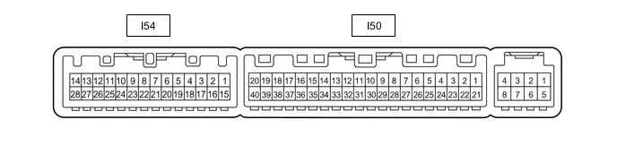
Tester Connection Wiring Color Terminal Description Condition Specified Condition I50-1 (IG+) - Body ground SB - Body ground IG power supply Engine switch on (IG) 11 to 14 V Engine switch off Below 1 V I50-14 (GND) - Body ground W-B - Body ground Ground Always Below 1 Ω I50-21 (B) - Body ground GR - Body ground Battery power supply Always 11 to 14 V -
Reconnect the I50 air conditioning amplifier assembly connector.
-
Measure the voltage and resistance according to the value(s) in the table below.
-
Check for pulse generation according to the value(s) in the table below.
Tester Connection Wiring Color Terminal Description Condition Specified Condition I50-16 (SHP+) - Body ground V - Body ground Seat heater (for Front Passenger Side) drive signal
-
Engine switch on (IG)
-
Seat heater switch (for Front Passenger Side) on
Below 1 V I50-17 (SHD+) - Body ground LG - Body ground Seat heater (for Driver Side) input signal
-
Engine switch on (IG)
-
Seat heater switch (for Driver Side) on
Below 1 V I50-37 (LIN1) - Body ground B - Body ground Seat heater switch signal Engine switch on (IG) Pulse generation I54-3 (TSR) - I54-7 (SG-3) P - R Seat heater sensor (for Front Passenger Side) input signal Engine switch off
(0 to 30°C [32 to 86°F])
26.74 to 8.411 kΩ I54-4 (TSL) - I54-8 (SG-6) W - G Seat heater sensor (for Driver Side) input signal Engine switch off
(0 to 30°C [32 to 86°F])
26.74 to 8.411 kΩ -
-
-
CHECK AIR CONDITIONING CONTROL ASSEMBLY