REAR POWER SEAT CONTROL SYSTEM Rear Door Courtesy Switch Circuit
DESCRIPTION
The fold seat control ECU receives the switch operation signal, driving condition signal and rear door open/close signal. Then the fold seat control ECU actives the rear seat according to these signals.
WIRING DIAGRAM
PROCEDURE
-
INSPECT REAR DOOR COURTESY LIGHT SWITCH ASSEMBLY
-
Remove the rear door courtesy light switch assembly.
-
Inspect the rear door courtesy light switch assembly.
Result Proceed to OK NG
NG 
REPLACE REAR DOOR COURTESY LIGHT SWITCH ASSEMBLY Click here
OK 
-
-
CHECK HARNESS AND CONNECTOR (FOLD SEAT CONTROL ECU - REAR DOOR COURTESY LIGHT SWITCH ASSEMBLY)
-
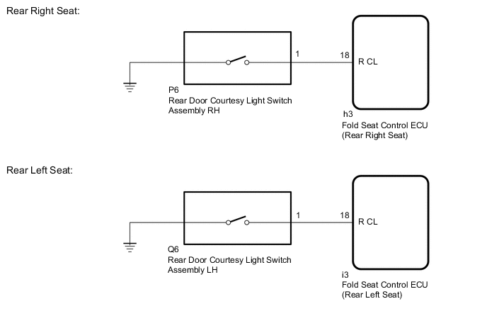
Rear Right Seat:
-
Disconnect the h3 fold seat control ECU (rear right seat) connector.
-
Disconnect the P6 rear door courtesy light switch assembly RH connector.
-
-
Rear Left Seat:
-
Disconnect the i3 fold seat control ECU (rear left seat) connector.
-
Disconnect the Q6 rear door courtesy light switch assembly LH connector.
-
-
Measure the resistance according to the value(s) in the table below.
Standard Resistance Rear Right Seat Tester Connection Condition Specified Condition h3-18 (R CL) - P6-1 Always Below 1 Ω h3-18 (R CL) or P6-1 - Body ground Always 10 kΩ or higher Rear Left Seat Tester Connection Condition Specified Condition i3-18 (R CL) - Q6-1 Always Below 1 Ω i3-18 (R CL) or Q6-1 - Body ground Always 10 kΩ or higher Result Proceed to OK NG
OK
PROCEED TO NEXT SUSPECTED AREA SHOWN IN PROBLEM SYMPTOMS TABLE Click here
NG
REPAIR OR REPLACE HARNESS OR CONNECTOR
-