PRE-COLLISION SYSTEM, Diagnostic DTC:C1A4B
| DTC Code | DTC Name |
|---|---|
| C1A4B | Stop Light Relay Circuit |
DESCRIPTION
The skid control ECU (brake actuator assembly) sends a stop light operation request signal to the stop light control ECU assembly. If the skid control ECU (brake actuator assembly) detects a malfunction in the stop light control ECU assembly circuit, the driving support ECU assembly stores DTC C1A4B.
| DTC No. | Detection Item | DTC Detection Condition | Trouble Area |
|---|---|---|---|
| C1A4B | Stop Light Relay Circuit | Diagnosis condition:
Malfunction condition: Either of the following conditions is met:
|
|
WIRING DIAGRAM
CAUTION / NOTICE / HINT
Note
-
Inspect the fuses for circuits related to this system before performing the following procedure.
-
When replacing the skid control ECU (brake actuator assembly), perform zero point calibration and store system information.
-
Before replacing the certification ECU (smart key ECU assembly), refer to Service Bulletin.
PROCEDURE
-
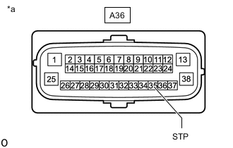
INSPECT TERMINAL VOLTAGE (SKID CONTROL ECU (BRAKE ACTUATOR ASSEMBLY) CONNECTOR)
-
Turn the engine switch off.
-
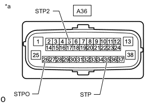
*a Front view of harness connector
(to Skid control ECU (brake actuator assembly))
Disconnect the skid control ECU (brake actuator assembly) connector.
-
Measure the voltage according to the value(s) in the table below.
Standard Voltage Tester Connection Condition Specified Condition A36-35 (STP) - Body ground Brake pedal depressed 11 to 14 V Brake pedal released Below 1.5 V A36-26 (STPO) - Body ground Engine switch on (IG) 11 to 14 V A36-5 (STP2) - Body ground Brake pedal depressed 11 to 14 V Brake pedal released Below 1.5 V -
Connect the skid control ECU (brake actuator assembly) connector.
Result Result Proceed to All terminal voltage is normal A Only STP terminal voltage abnormal B Only STPO terminal voltage abnormal C Only STP2 terminal voltage abnormal D STPO terminal and STP2 terminal voltage abnormal E
B 
INSPECT TERMINAL VOLTAGE (SKID CONTROL ECU (BRAKE ACTUATOR ASSEMBLY) - ECM) Click here
C
CHECK HARNESS AND CONNECTOR (SKID CONTROL ECU (BRAKE ACTUATOR ASSEMBLY) - STOP LIGHT CONTROL ECU ASSEMBLY) Click here
D
INSPECT TERMINAL VOLTAGE (SKID CONTROL ECU (BRAKE ACTUATOR ASSEMBLY) - REAR COMBINATION LIGHT ASSEMBLY LH) Click here
E
CHECK HARNESS AND CONNECTOR (+B/GND TERMINAL) Click here
A 
-
-
PERFORM ACTIVE TEST USING GTS (STOP LIGHT RELAY)
-
Turn the engine switch off.
-
Enter the following menus: Chassis / ABS/VSC/TRC / Active Test.
-
Perform "Active Test" according to the display on the GTS.
Chassis > ABS/VSC/TRC > Active TestTester Display Measurement Item Control Range Diagnostic Note Stop Light Relay Stop light control ECU assembly ON or OFF Stop lights come on
Chassis > ABS/VSC/TRC > Active TestTester Display Stop Light Relay OK Stop light turns ON/OFF in response to the GTS operation Result Proceed to OK NG
NG
INSPECT SKID CONTROL ECU (BRAKE ACTUATOR ASSEMBLY) Click here
OK
-
-
CHECK FOR DTC
-
Clear the DTCs.
Body Electrical > Pre-Collision 2 > Clear DTCs -
Enter the following menus: Chassis / ABS/VSC/TRC / Active Test.
-
Perform "Active Test" according to the display on the GTS.
Chassis > ABS/VSC/TRC > Active TestTester Display Measurement Item Control Range Diagnostic Note Stop Light Relay Stop light control ECU assembly ON or OFF Stop lights come on
Chassis > ABS/VSC/TRC > Active TestTester Display Stop Light Relay -
Check for DTCs.
Body Electrical > Pre-Collision 2 > Trouble CodesResult Result Proceed to DTC C1A4B is output. A DTC C1A4B is not output. B
A 
USE SIMULATION METHOD TO CHECK Click here
B
REPLACE SKID CONTROL ECU (BRAKE ACTUATOR ASSEMBLY) Click here
-
-
INSPECT SKID CONTROL ECU (BRAKE ACTUATOR ASSEMBLY)
-
Enter the following menus: Chassis / ABS/VSC/TRC / Active Test.
-
Perform "Active Test" according to the display on the GTS.
Chassis > ABS/VSC/TRC > Active TestTester Display Measurement Item Control Range Diagnostic Note Stop Light Relay Stop light control ECU assembly ON or OFF Stop lights come on
Chassis > ABS/VSC/TRC > Active TestTester Display Stop Light Relay -
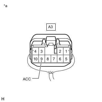
*a Component with harness connected (Stop Light Switch Assembly) Measure the voltage according to the value(s) in the table below.
Standard Voltage Tester Connection Condition Specified Condition A3-9 (ACC) - Body ground Active Test is ON Below 1.5 V Result Proceed to OK NG
OK
REPLACE STOP LIGHT CONTROL ECU ASSEMBLY for LHD: Click here
REPLACE STOP LIGHT CONTROL ECU ASSEMBLY for RHD: Click hereNG
REPLACE SKID CONTROL ECU (BRAKE ACTUATOR ASSEMBLY) Click here
-
-
INSPECT TERMINAL VOLTAGE (SKID CONTROL ECU (BRAKE ACTUATOR ASSEMBLY) - ECM)
-
Turn the engine switch off.
-
*a Front view of harness connector
(to Skid control ECU (brake actuator assembly))
Disconnect the skid control ECU (brake actuator assembly) connector.
-
Disconnect the A35 ECM connector.
-
Measure the voltage according to the value(s) in the table below.
Standard Voltage Tester Connection Condition Specified Condition A36-35 (STP) - Body ground Brake pedal depressed 8 to 14 V A36-35 (STP) - Body ground Brake pedal released Below 1.5 V -
Connect the A35 ECM connector.
-
Connect the skid control ECU (brake actuator assembly) connector.
Result Proceed to OK NG
OK
REPLACE ECM Click here
NG
-
-
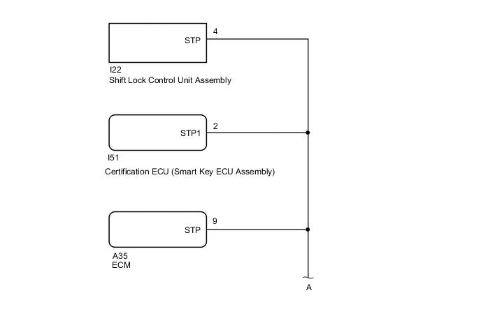
INSPECT TERMINAL VOLTAGE (SKID CONTROL ECU (BRAKE ACTUATOR ASSEMBLY) - SHIFT LOCK CONTROL UNIT ASSEMBLY)
-
Turn the engine switch off.
-
*a Front view of harness connector
(to Skid control ECU (brake actuator assembly))
Disconnect the skid control ECU (brake actuator assembly) connector.
-
Disconnect the A35 ECM connector.
-
Disconnect the I22 shift lock control unit assembly connector.
-
Measure the voltage according to the value(s) in the table below.
Standard Voltage Tester Connection Condition Specified Condition A36-35 (STP) - Body ground Brake pedal depressed 8 to 14 V A36-35 (STP) - Body ground Brake pedal released Below 1.5 V -
Connect the I22 shift lock control unit assembly connector.
-
Connect the A35 ECM connector.
-
Connect the skid control ECU (brake actuator assembly) connector.
Result Proceed to OK NG
OK
REPLACE SHIFT LOCK CONTROL UNIT ASSEMBLY Click here
NG
-
-
INSPECT TERMINAL VOLTAGE (SKID CONTROL ECU (BRAKE ACTUATOR ASSEMBLY) - CERTIFICATION ECU (SMART KEY ECU ASSEMBLY))
-
Turn the engine switch off.
-
*a Front view of harness connector
(to Skid control ECU (brake actuator assembly))
Disconnect the skid control ECU (brake actuator assembly) connector.
-
Disconnect the A35 ECM connector.
-
Disconnect the I22 shift lock control unit assembly connector.
-
Disconnect the I51 certification ECU (smart key ECU assembly) connector.
-
Measure the voltage according to the value(s) in the table below.
Standard Voltage Tester Connection Condition Specified Condition A36-35 (STP) - Body ground Brake pedal depressed 8 to 14 V A36-35 (STP) - Body ground Brake pedal released Below 1.5 V -
Connect the I51 certification ECU (smart key ECU assembly) connector.
-
Connect the I22 shift lock control unit assembly connector.
-
Connect the A35 ECM connector.
-
Connect the skid control ECU (brake actuator assembly) connector.
Result Proceed to OK NG
OK
REPLACE CERTIFICATION ECU (SMART KEY ECU ASSEMBLY)
NG
-
-
INSPECT TERMINAL VOLTAGE (SKID CONTROL ECU (BRAKE ACTUATOR ASSEMBLY) - STOP LIGHT CONTROL ECU ASSEMBLY)
-
Turn the engine switch off.
-
*a Front view of harness connector
(to Skid control ECU (brake actuator assembly))
Disconnect the skid control ECU (brake actuator assembly) connector.
-
Disconnect the A35 ECM connector.
-
Disconnect the I22 shift lock control unit assembly connector.
-
Disconnect the I51 certification ECU (smart key ECU assembly) connector.
-
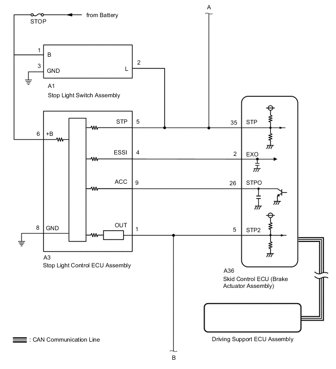
Disconnect the A3 stop light control ECU assembly connector.
-
Measure the voltage according to the value(s) in the table below.
Standard Voltage Tester Connection Condition Specified Condition A36-35 (STP) - Body ground Brake pedal depressed 8 to 14 V A36-35 (STP) - Body ground Brake pedal released Below 1.5 V -
Connect the A3 stop light control ECU assembly connector.
-
Connect the I51 certification ECU (smart key ECU assembly) connector.
-
Connect the I22 shift lock control unit assembly connector.
-
Connect the A35 ECM connector.
-
Connect the skid control ECU (brake actuator assembly) connector.
Result Proceed to OK NG
OK
REPLACE STOP LIGHT CONTROL ECU ASSEMBLY for LHD: Click here
REPLACE STOP LIGHT CONTROL ECU ASSEMBLY for RHD: Click hereNG
-
-
INSPECT TERMINAL VOLTAGE (SKID CONTROL ECU (BRAKE ACTUATOR ASSEMBLY) - STOP LIGHT SWITCH ASSEMBLY)
-
Turn the engine switch off.
-
*a Front view of harness connector
(to Skid control ECU (brake actuator assembly))
Disconnect the skid control ECU (brake actuator assembly) connector.
-
Disconnect the A35 ECM connector.
-
Disconnect the I22 shift lock control unit assembly connector.
-
Disconnect the I51 certification ECU (smart key ECU assembly) connector.
-
Disconnect the A3 stop light control ECU assembly connector.
-
Disconnect the A1 stop light switch assembly connector.
-
Measure the voltage according to the value(s) in the table below.
Standard Voltage Tester Connection Condition Specified Condition A36-35 (STP) - Body ground Always Below 1.5 V -
Connect the A1 stop light switch assembly connector.
-
Connect the A3 stop light control ECU assembly connector.
-
Connect the I51 certification ECU (smart key ECU assembly) connector.
-
Connect the I22 shift lock control unit assembly connector.
-
Connect the A35 ECM connector.
-
Connect the skid control ECU (brake actuator assembly) connector.
Result Proceed to OK NG
NG
REPAIR OR REPLACE HARNESS OR CONNECTOR
OK
-
-
CHECK HARNESS AND CONNECTOR (SKID CONTROL ECU (BRAKE ACTUATOR ASSEMBLY) - STOP LIGHT SWITCH ASSEMBLY)
-
Turn the engine switch off.
-
Disconnect the A36 skid control ECU (brake actuator assembly) connector.
-
Disconnect the A1 stop light switch assembly connector.
-
Measure the resistance according to the value(s) in the table below.
Standard Resistance Tester Connection Condition Specified Condition A36-35 (STP) - A1-2 (L) Always Below 1 Ω A36-35 (STP) or A1-2 (L) - Body ground Always 10 kΩ or higher -
Connect the A1 stop light switch assembly connector.
-
Connect the A36 skid control ECU (brake actuator assembly) connector.
Result Proceed to OK NG
OK
REPLACE STOP LIGHT SWITCH ASSEMBLY Click here
NG
REPAIR OR REPLACE HARNESS OR CONNECTOR
-
-
CHECK HARNESS AND CONNECTOR (SKID CONTROL ECU (BRAKE ACTUATOR ASSEMBLY) - STOP LIGHT CONTROL ECU ASSEMBLY)
-
Turn the engine switch off.
-
Disconnect the A36 skid control ECU (brake actuator assembly) connector.
-
Disconnect the A3 stop light control ECU assemblyconnector.
-
Measure the resistance according to the value(s) in the table below.
Standard Resistance Tester Connection Condition Specified Condition A36-26 (STPO) - A3-9 (ACC) Always Below 1 Ω -
Connect the A3 stop light control ECU assemblyconnector.
-
Connect the A36 skid control ECU (brake actuator assembly) connector.
Result Proceed to OK NG
OK
REPLACE STOP LIGHT CONTROL ECU ASSEMBLY for LHD: Click here
REPLACE STOP LIGHT CONTROL ECU ASSEMBLY for RHD: Click hereNG
REPAIR OR REPLACE HARNESS OR CONNECTOR
-
-
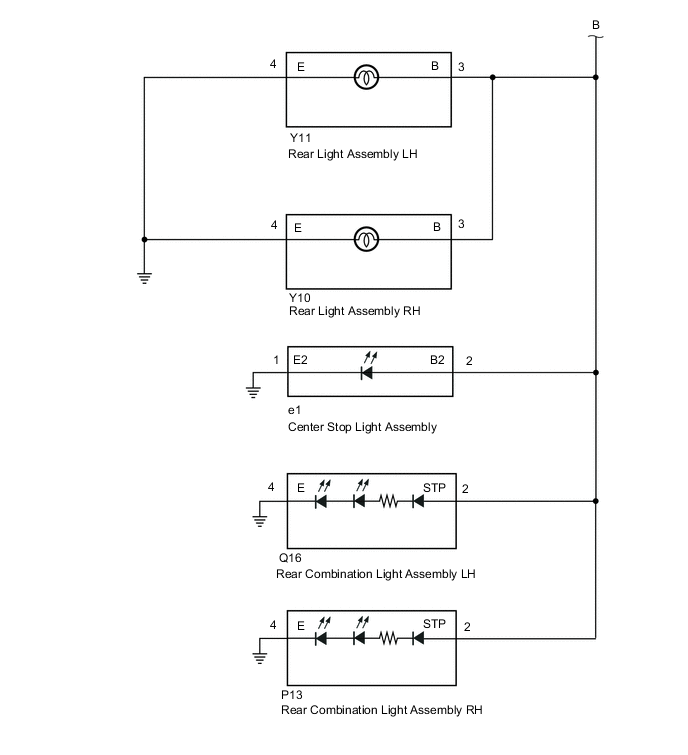
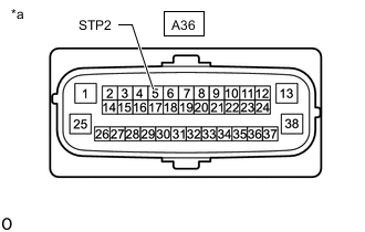
INSPECT TERMINAL VOLTAGE (SKID CONTROL ECU (BRAKE ACTUATOR ASSEMBLY) - REAR COMBINATION LIGHT ASSEMBLY LH)
-
Turn the engine switch off.
-
*a Front view of harness connector
(to Skid control ECU (brake actuator assembly))
Disconnect the skid control ECU (brake actuator assembly) connector.
-
Disconnect the Q16 rear combination light assembly LH connector.
-
Measure the voltage according to the value(s) in the table below.
Standard Voltage Tester Connection Condition Specified Condition A36-5 (STP2) - Body ground Brake pedal depressed 8 to 14 V A36-5 (STP2) - Body ground Brake pedal released Below 1.5 V -
Connect the Q16 rear combination light assembly LH connector.
-
Connect the skid control ECU (brake actuator assembly) connector.
Result Proceed to OK NG
OK
REPLACE REAR COMBINATION LIGHT ASSEMBLY LH Click here
NG
-
-
INSPECT TERMINAL VOLTAGE (SKID CONTROL ECU (BRAKE ACTUATOR ASSEMBLY) - REAR COMBINATION LIGHT ASSEMBLY RH)
-
Turn the engine switch off.
-
*a Front view of harness connector
(to Skid control ECU (brake actuator assembly))
Disconnect the skid control ECU (brake actuator assembly) connector.
-
Disconnect the Q16 rear combination light assembly LH connector.
-
Disconnect the P13 rear combination light assembly RH connector.
-
Measure the voltage according to the value(s) in the table below.
Standard Voltage Tester Connection Condition Specified Condition A36-5 (STP2) - Body ground Brake pedal depressed 8 to 14 V A36-5 (STP2) - Body ground Brake pedal released Below 1.5 V -
Connect the P13 rear combination light assembly RH connector.
-
Connect the Q16 rear combination light assembly LH connector.
-
Connect the skid control ECU (brake actuator assembly) connector.
Result Proceed to OK NG
OK
REPLACE REAR COMBINATION LIGHT ASSEMBLY RH Click here
NG
-
-
INSPECT TERMINAL VOLTAGE (SKID CONTROL ECU (BRAKE ACTUATOR ASSEMBLY) - REAR LIGHT ASSEMBLY LH)
-
Turn the engine switch off.
-
*a Front view of harness connector
(to Skid control ECU (brake actuator assembly))
Disconnect the skid control ECU (brake actuator assembly) connector.
-
Disconnect the Q16 rear combination light assembly LH connector.
-
Disconnect the P13 rear combination light assembly RH connector.
-
Disconnect the Y11 rear light assembly LH connector.
-
Measure the voltage according to the value(s) in the table below.
Standard Voltage Tester Connection Condition Specified Condition A36-5 (STP2) - Body ground Brake pedal depressed 8 to 14 V A36-5 (STP2) - Body ground Brake pedal released Below 1.5 V -
Connect the Y11 rear light assembly LH connector.
-
Connect the P13 rear combination light assembly RH connector.
-
Connect the Q16 rear combination light assembly LH connector.
-
Connect the skid control ECU (brake actuator assembly) connector.
Result Proceed to OK NG
OK
REPLACE REAR LIGHT ASSEMBLY LH Click here
NG
-
-
INSPECT TERMINAL VOLTAGE (SKID CONTROL ECU (BRAKE ACTUATOR ASSEMBLY) - REAR LIGHT ASSEMBLY RH)
-
Turn the engine switch off.
-
*a Front view of harness connector
(to Skid control ECU (brake actuator assembly))
Disconnect the skid control ECU (brake actuator assembly) connector.
-
Disconnect the Q16 rear combination light assembly LH connector.
-
Disconnect the P13 rear combination light assembly RH connector.
-
Disconnect the Y11 rear light assembly LH connector.
-
Disconnect the Y10 rear light assembly RH connector.
-
Measure the voltage according to the value(s) in the table below.
Standard Voltage Tester Connection Condition Specified Condition A36-5 (STP2) - Body ground Brake pedal depressed 8 to 14 V A36-5 (STP2) - Body ground Brake pedal released Below 1.5 V -
Connect the Y10 rear light assembly RH connector.
-
Connect the Y11 rear light assembly LH connector.
-
Connect the P13 rear combination light assembly RH connector.
-
Connect the Q16 rear combination light assembly LH connector.
-
Connect the skid control ECU (brake actuator assembly) connector.
Result Proceed to OK NG
OK
REPLACE REAR LIGHT ASSEMBLY RH Click here
NG
-
-
INSPECT TERMINAL VOLTAGE (SKID CONTROL ECU (BRAKE ACTUATOR ASSEMBLY) - CENTER STOP LIGHT ASSEMBLY)
-
Turn the engine switch off.
-
*a Front view of harness connector
(to Skid control ECU (brake actuator assembly))
Disconnect the skid control ECU (brake actuator assembly) connector.
-
Disconnect the Q16 rear combination light assembly LH connector.
-
Disconnect the P13 rear combination light assembly RH connector.
-
Disconnect the Y11 rear light assembly LH connector.
-
Disconnect the Y10 rear light assembly RH connector.
-
Disconnect the e1 center stop light assembly connector.
-
Measure the voltage according to the value(s) in the table below.
Standard Voltage Tester Connection Condition Specified Condition A36-5 (STP2) - Body ground Brake pedal depressed 8 to 14 V A36-5 (STP2) - Body ground Brake pedal released Below 1.5 V -
Connect the e1 center stop light assembly connector.
-
Connect the Y10 rear light assembly RH connector.
-
Connect the Y11 rear light assembly LH connector.
-
Connect the P13 rear combination light assembly RH connector.
-
Connect the Q16 rear combination light assembly LH connector.
-
Connect the skid control ECU (brake actuator assembly) connector.
Result Proceed to OK NG
OK
REPLACE CENTER STOP LIGHT ASSEMBLY Click here
NG
-
-
INSPECT TERMINAL VOLTAGE (SKID CONTROL ECU (BRAKE ACTUATOR ASSEMBLY) - STOP LIGHT CONTROL ECU ASSEMBLY)
-
Turn the engine switch off.
-
*a Front view of harness connector
(to Skid control ECU (brake actuator assembly))
Disconnect the skid control ECU (brake actuator assembly) connector.
-
Disconnect the Q16 rear combination light assembly LH connector.
-
Disconnect the P13 rear combination light assembly RH connector.
-
Disconnect the Y11 rear light assembly LH connector.
-
Disconnect the Y10 rear light assembly RH connector.
-
Disconnect the e1 center stop light assembly connector.
-
Disconnect the A3 stop light control ECU assembly connector.
-
Measure the voltage according to the value(s) in the table below.
Standard Voltage Tester Connection Condition Specified Condition A36-5 (STP2) - Body ground Always Below 1.5 V -
Connect the A3 stop light control ECU assembly connector.
-
Connect the e1 center stop light assembly connector.
-
Connect the Y10 rear light assembly RH connector.
-
Connect the Y11 rear light assembly LH connector.
-
Connect the P13 rear combination light assembly RH connector.
-
Connect the Q16 rear combination light assembly LH connector.
-
Connect the skid control ECU (brake actuator assembly) connector.
Result Proceed to OK NG
NG
REPAIR OR REPLACE HARNESS OR CONNECTOR
OK
-
-
CHECK HARNESS AND CONNECTOR (+B/GND TERMINAL)
-
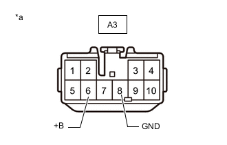
*a Front view of harness connector
(to Stop light control ECU assembly )
Turn the engine switch off.
-
Disconnect the A3 stop light control ECU assembly connector.
-
Measure the voltage according to the value(s) in the table below.
Standard Voltage Tester Connection Condition Specified Condition A3-6 (+B) - Body ground Always 11 to 14V -
Measure the resistance according to the value(s) in the table below.
Standard Resistance Tester Connection Condition Specified Condition A3-8 (GND) - Body ground Always Below 1 Ω -
Connect the A3 stop light control ECU assembly connector.
Result Proceed to OK NG
NG
REPAIR OR REPLACE HARNESS OR CONNECTOR
OK
-
-
CHECK HARNESS AND CONNECTOR (SKID CONTROL ECU (BRAKE ACTUATOR ASSEMBLY) - STOP LIGHT CONTROL ECU ASSEMBLY)
-
Turn the engine switch off.
-
Disconnect the A36 skid control ECU (brake actuator assembly) connector.
-
Disconnect the A3 stop light control ECU assembly connector.
-
Measure the resistance according to the value(s) in the table below.
Standard Resistance Tester Connection Condition Specified Condition A3-1 (OUT) - A36-5 (STP2) Always Below 1 Ω A3-1 (OUT) or A36-5 (STP2) - Body ground Always 10 kΩ or higher -
Connect the A3 stop light control ECU assembly connector.
-
Connect the A36 skid control ECU (brake actuator assembly) connector.
Result Proceed to OK NG
OK
REPLACE STOP LIGHT CONTROL ECU ASSEMBLY for LHD: Click here
REPLACE STOP LIGHT CONTROL ECU ASSEMBLY for RHD: Click hereNG
REPAIR OR REPLACE HARNESS OR CONNECTOR
-
-
CHECK HARNESS AND CONNECTOR (+B/GND TERMINAL)
-

*a Front view of harness connector
(to Stop light control ECU assembly )
Turn the engine switch off.
-
Disconnect the A3 stop light control ECU assembly connector.
-
Measure the voltage according to the value(s) in the table below.
Standard Voltage Tester Connection Condition Specified Condition A3-6 (+B) - Body ground Always 11 to 14V -
Measure the resistance according to the value(s) in the table below.
Standard Resistance Tester Connection Condition Specified Condition A3-8 (GND) - Body ground Always Below 1 Ω -
Connect the A3 stop light control ECU assembly connector.
Result Proceed to OK NG
NG
REPAIR OR REPLACE HARNESS OR CONNECTOR
OK
-
-
CHECK HARNESS AND CONNECTOR (SKID CONTROL ECU (BRAKE ACTUATOR ASSEMBLY) - STOP LIGHT CONTROL ECU ASSEMBLY)
-
Turn the engine switch off.
-
Disconnect the A36 skid control ECU (brake actuator assembly) connector.
-
Disconnect the A3 stop light control ECU assembly connector.
-
Measure the resistance according to the value(s) in the table below.
Standard Resistance Tester Connection Condition Specified Condition A3-1 (OUT) - A36-5 (STP2) Always Below 1 Ω A3-1 (OUT) or A36-5 (STP2) - Body ground Always 10 kΩ or higher -
Connect the A3 stop light control ECU assembly connector.
-
Connect the A36 skid control ECU (brake actuator assembly) connector.
Result Proceed to OK NG
OK
REPLACE STOP LIGHT CONTROL ECU ASSEMBLY Click here
NG
REPAIR OR REPLACE HARNESS OR CONNECTOR
-