PRE-CRASH SAFETY SYSTEM CANCEL SWITCH INSPECTION
PROCEDURE
-
INSPECT NO. 2 COMBINATION SWITCH ASSEMBLY
-
Remove the No. 2 combination switch assembly.
-
Check the resistance.
-
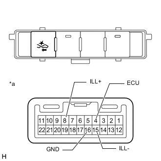
*a Component without harness connected
(No. 2 Combination Switch Assembly)
Measure the resistance according to the value(s) in the table below.
Standard Resistance Tester Connection Switch Condition Specified Condition 4 (ECU) - 16 (GND) Pre-crash safety system cancel switch on Below 1 Ω 4 (ECU) - 16 (GND) Pre-crash safety system cancel switch off 10 kΩ or higher If the result is not as specified, replace the No. 2 combination switch assembly.
-
-
Inspect the illumination operation.
-
Apply battery voltage to the No. 2 combination switch assembly connector, and check that the No. 2 combination switch assembly LED illuminates.
OK Measurement Condition Specified Condition Battery positive (+) → Terminal 8 (ILL+)
Battery negative (-) → Terminal 15 (ILL-)
LED illuminates If the result is not as specified, replace the No. 2 combination switch assembly.
-
-