AIRBAG SYSTEM SRS Warning Light does not Come ON
CAUTION / NOTICE / HINT
Note
-
After turning the engine switch off, waiting time may be required before disconnecting the cable from the negative (-) battery terminal. Therefore, make sure to read the disconnecting the cable from the negative (-) battery terminal notices before proceeding with work.
-
When disconnecting the cable from the negative (-) battery terminal while performing repairs, some systems need to be initialized after the cable is reconnected.
-
After replacing the airbag ECU assembly, refer to initialization.
-
Inspect the fuses for circuits related to this system before performing the following inspection procedure.
-
When replacing the combination meter assembly, make sure to replace it with a new one.
PROCEDURE
-
CHECK BATTERY
-
Measure the battery voltage.
Standard voltage 11 to 14 V Tech Tips
-
It may be possible to tell whether the battery is discharged by operating the horn.
-
If the voltage is below 11 V, recharge or replace the battery before proceeding to the next step.
Result Proceed to OK NG -
NG 
REPLACE OR RECHARGE BATTERY
OK 
-
-
CHECK CONNECTION OF CONNECTOR
-
Turn the engine switch off.
-
Disconnect the cable from the negative (-) battery terminal, and wait for at least 90 seconds.
-
Check that the connector is properly connected to the combination meter assembly.
Result Proceed to The connector is properly connected The connector is not properly connected
The connector is not properly connected
CONNECT CONNECTOR PROPERLY
The connector is properly connected
-
-
CHECK HARNESS AND CONNECTOR (COMBINATION METER ASSEMBLY - BATTERY AND BODY GROUND)
-
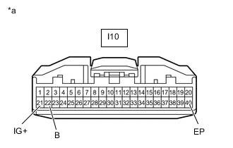
*a Front view of wire harness connector
(to Combination Meter Assembly)
Disconnect the cable from the negative (-) battery terminal, and wait for at least 90 seconds.
-
Disconnect the connector from the combination meter assembly.
-
Connect the cable to the negative (-) battery terminal, and wait for at least 2 seconds.
-
Turn the engine switch on (IG).
-
Measure the voltage according to the value(s) in the table below.
Standard Voltage w/ Stop and Start System Tester Connection Switch Condition Specified Condition I10-21 (IG+) - Body ground Engine switch on (IG) 10.5 to 16 V I10-22 (B) - Body ground Engine switch off 11 to 14 V w/o Stop and Start System Tester Connection Switch Condition Specified Condition I10-21 (IG+) - Body ground Engine switch on (IG) 11 to 14 V I10-22 (B) - Body ground Engine switch off 11 to 14 V -
Measure the resistance according to the value(s) in the table below.
Standard Resistance Tester Connection Condition Specified Condition I10-40 (EP) - Body ground Always Below 1 Ω Result Proceed to OK NG (w/ Stop and Start System) NG (w/o Stop and Start System)
NG (w/ Stop and Start System)
GO TO STOP AND START SYSTEM Click here
NG (w/o Stop and Start System)
REPAIR OR REPLACE HARNESS OR CONNECTOR
OK
-
-
CHECK SRS WARNING LIGHT (SHORT TO GROUND)
-
Turn the engine switch off.
-
Disconnect the cable from the negative (-) battery terminal, and wait for at least 90 seconds.
-
Connect the connector to the combination meter assembly.
-
Connect the cable to the negative (-) battery terminal, and wait for at least 2 seconds.
-
Turn the engine switch on (IG).
-
Check the SRS warning light condition.
OK After the primary check period, the SRS warning light goes off for approximately 10 seconds and then remains on. Tech Tips
The primary check period is approximately 6 seconds after the engine switch is turned on (IG).
Result Proceed to OK NG
OK
REPLACE AIRBAG ECU ASSEMBLY Click here
NG
GO TO METER / GAUGE SYSTEM Click here
-