HEADUP DISPLAY SYSTEM Main Switch Circuit
DESCRIPTION
The headup display switch assembly and meter mirror sub-assembly are connected via direct line. The meter mirror sub-assembly can be turned off and on by operating the headup display switchassembly.
WIRING DIAGRAM
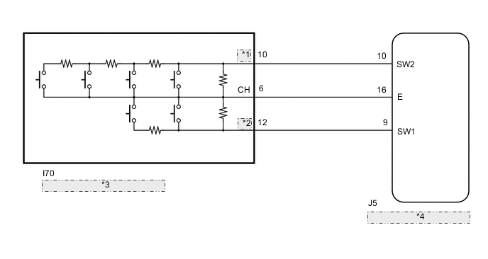
| *1 | ILD |
| *2 | ILU |
| *3 | Headup Display Switch Assembly |
| *4 | Meter Mirror Sub-assembly |
PROCEDURE
-
READ VALUE USING GTS (MAIN SWITCH)
-
Connect the GTS to the DLC3.
-
Turn the engine switch on (IG).
-
Turn the GTS on.
-
Enter the following menus: Body Electrical / Head Up Display / Data List.
-
Read the Data List according to the display on the GTS.
Body Electrical > Head Up Display > Data ListTester Display Measurement Item Range Normal Condition Diagnostic Note Main Switch Main switch OFF or ON OFF: Switch released
ON: Switch pushed
- Brightness Up Switch Brightness up switch OFF or ON OFF: Switch released
ON: Switch pushed
- Brightness Down Switch Brightness down switch OFF or ON OFF: Switch released
ON: Switch pushed
- Projection Position Up Switch Projection position up switch OFF or ON OFF: Switch released
ON: Switch pushed
- Projection Position Down Switch Projection position down switch OFF or ON OFF: Switch released
ON: Switch pushed
- Display Change Switch Display change switch OFF or ON OFF: Switch released
ON: Switch pushed
- OK Headup display switch assembly condition displayed on the GTS changes with the actual switch operation.
Body Electrical > Head Up Display > Data ListTester Display Main Switch Brightness Up Switch Brightness Down Switch Projection Position Up Switch Projection Position Down Switch Display Change Switch Result Proceed to OK NG
OK 
REPLACE METER MIRROR SUB-ASSEMBLY Click here
NG 
-
-
INSPECT HEADUP DISPLAY SWITCH ASSEMBLY
-
Remove the headup display switch assembly.
-
Inspect the headup display switch assembly.
Result Proceed to OK NG
NG
REPLACE HEADUP DISPLAY SWITCH ASSEMBLY Click here
OK
-
-
CHECK HARNESS AND CONNECTOR (METER MIRROR SUB-ASSEMBLY - HEADUP DISPLAY SWITCH ASSEMBLY)
-
Disconnect the J5 meter mirror sub-assembly connector.
-
Disconnect the I70 headup display switch assembly) connector.
-
Measure the resistance according to the value(s) in the table below.
Standard Resistance Tester Connection Condition Specified Condition J5-9(SW1) - I70-12(ILU) Always Below 1 Ω J5-10(SW2) - I70-10(ILD) Always Below 1 Ω J5-16(E) - I70-6(CH) Always Below 1 Ω J5-9(SW1) or I70-12(ILU) - Body ground Always 10 kΩ or higher J5-10(SW2) or I70-10(ILD) - Body ground Always 10 kΩ or higher J5-16(E) or I70-6(CH) - Body ground Always 10 kΩ or higher Result Proceed to OK NG
OK
REPLACE METER MIRROR SUB-ASSEMBLY Click here
NG
REPAIR OR REPLACE HARNESS OR CONNECTOR
-