METER / GAUGE SYSTEM Speed Signal Circuit
DESCRIPTION
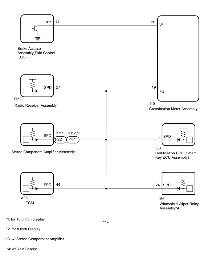
The combination meter assembly receives the vehicle speed signal from this circuit. The wheel speed sensors produce an output that varies according to the vehicle speed. The wheel speed sensor output is received by the brake actuator assembly (skid control ECU) which uses this information to create the vehicle speed signal*. The vehicle speed signal consists of pulses sent to the combination meter assembly from the brake actuator assembly (skid control ECU). To create this signal, 12 V is output from IG2 which is behind a resistor in the combination meter assembly. This voltage is sent to the brake actuator assembly (skid control ECU). The pulse signal is created by switching the transistor in the brake actuator assembly (skid control ECU) on and off, making the voltage on the wire drop to 0 V. A similar system is used for the output of this signal from the combination meter assembly via terminal +S. A voltage of 12 V or 5 V is applied to terminal +S from each ECU or relay that is connected to this terminal. The transistor in the combination meter assembly is controlled by the signal from the brake actuator assembly (skid control ECU). When this transistor is turned on, this transistor makes the voltage supplied by the various ECUs (via their respective internal resistors) drop to 0 V. Each ECU connected to terminal +S of the combination meter assembly controls its respective system based on this pulse signal.
-
*: This vehicle speed signal is created by the brake actuator assembly (skid control ECU). There is no actual component that is referred to as the vehicle speed sensor. In addition, for some systems, vehicle speed information may be received via CAN communication.
Tech Tips
This circuit is used for the systems connected to terminal +S. This signal is not used for combination meter assembly operation. Combination meter assembly components such as the speedometer operate using data received via CAN communication.
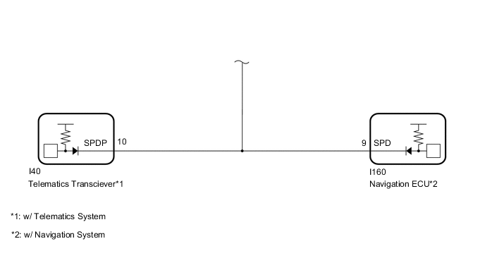
WIRING DIAGRAM
CAUTION / NOTICE / HINT
Note
When replacing the combination meter assembly, make sure to replace it with a new one.
PROCEDURE
-
CHECK RADIO RECEIVER ASSEMBLY
-
*1: for 10.3 Inch Display
*2: for 8 Inch Display
*3: w/ Stereo Component Amplifier
*4: w/ Rain Sensor
*5: w/ Telematics System
*6: w/ Navigation System
-

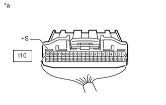
*a Rear view of wire harness connector
(to Combination Meter Assembly)
Disconnect the combination meter assembly connector.
-
Disconnect the P22*1 or P47*2 stereo component amplifier assembly connector.*3
-
Disconnect the I53 certification ECU (smart key ECU assembly) connector.
-
Disconnect the A35 ECM connector.
-
Disconnect the I56 windshield wiper relay assembly connector.*4
-
Disconnect the I40 telematics transceiver connector.*5
-
Disconnect the I160 navigationECU connector.*6
-
Measure the voltage according to the value(s) in the table below.
Standard Voltage Tester Connection Switch Condition Specified Condition I10-19 (+S) - Body ground Engine switch on (IG) 4.5 to 14 V Result Result Proceed to OK (w/ Stereo Component Amplifier) A OK (w/o Stereo Component Amplifier) B NG C
B 
GO TO STEP 3 Click here
C
CHECK HARNESS AND CONNECTOR (COMBINATION METER ASSEMBLY - RADIO RECEIVER ASSEMBLY) Click here
A 
-
-
CHECK STEREO COMPONENT AMPLIFIER ASSEMBLY
-
*1: for 10.3 Inch Display
*2: for 8 Inch Display
*3: w/ Stereo Component Amplifier
*4: w/ Telematics System
*5: w/ Navigation System
-
*a Rear view of wire harness connector
(to Combination Meter Assembly)
Disconnect the combination meter assembly connector.
-
Disconnect the I152 radio receiver assembly connector.
-
Disconnect the I53 certification ECU (smart key ECU assembly) connector.
-
Disconnect the A35 ECM connector.
-
Disconnect the I56 windshield wiper relay assembly connector.*3
-
Disconnect the I40 telematics transceiver connector.*4
-
Disconnect the I160 navigationECU connector.*5
-
Measure the voltage according to the value(s) in the table below.
Standard Voltage Tester Connection Switch Condition Specified Condition I10-19 (+S) - Body ground Engine switch on (IG) 4.5 to 14 V Result Proceed to OK NG
NG
CHECK HARNESS AND CONNECTOR (COMBINATION METER ASSEMBLY - STEREO COMPONENT AMPLIFIER ASSEMBLY) Click here
OK
-
-
CHECK CERTIFICATION ECU (SMART KEY ECU ASSEMBLY)
-
*1: for 10.3 Inch Display
*2: for 8 Inch Display
*3: w/ Stereo Component Amplifier
*4: w/ Rain Sensor
*5: w/ Telematics System
*6: w/ Navigation System
-
*a Rear view of wire harness connector
(to Combination Meter Assembly)
Disconnect the combination meter assembly connector.
-
Disconnect the I152 radio receiver assembly connector.
-
Disconnect the P22*1 or P47*2 stereo component amplifier assembly connector.*3
-
Disconnect the A35 ECM connector.
-
Disconnect the I56 windshield wiper relay assembly connector.*4
-
Disconnect the I40 telematics transceiver connector.*5
-
Disconnect the I160 navigationECU connector.*6
-
Measure the voltage according to the value(s) in the table below.
Standard Voltage Tester Connection Switch Condition Specified Condition I10-19 (+S) - Body ground Engine switch on (IG) 4.5 to 14 V Result Result Proceed to OK (w/ Rain Sensor) A OK (w/o Rain Sensor) B NG C
B
GO TO STEP 5 Click here
C
CHECK HARNESS AND CONNECTOR (COMBINATION METER ASSEMBLY - CERTIFICATION ECU [SMART KEY ECU ASSEMBLY]) Click here
A
-
-
CHECK WINDSHIELD WIPER RELAY ASSEMBLY
-
*1: for 10.3 Inch Display
*2: for 8 Inch Display
*3: w/ Stereo Component Amplifier
*4: w/ Telematics System
*5: w/ Navigation System
-
*a Rear view of wire harness connector
(to Combination Meter Assembly)
Disconnect the combination meter assembly connector.
-
Disconnect the I152 radio receiver assembly connector.
-
Disconnect the P22*1 or P47*2 stereo component amplifier assembly connector.*3
-
Disconnect the I53 certification ECU (smart key ECU assembly) connector.
-
Disconnect the A35 ECM connector.
-
Disconnect the I40 telematics transceiver connector.*4
-
Disconnect the I160 navigationECU connector.*5
-
Measure the voltage according to the value(s) in the table below.
Standard Voltage Tester Connection Switch Condition Specified Condition I10-19 (+S) - Body ground Engine switch on (IG) 4.5 to 14 V Result Proceed to OK NG
NG
CHECK HARNESS AND CONNECTOR (COMBINATION METER ASSEMBLY - WINDSHIELD WIPER RELAY ASSEMBLY) Click here
OK
-
-
CHECK ECM
-
*1: for 10.3 Inch Display
*2: for 8 Inch Display
*3: w/ Stereo Component Amplifier
*4: w/ Rain Sensor
*5: w/ Telematics System
*6: w/ Navigation System
-
*a Rear view of wire harness connector
(to Combination Meter Assembly)
Disconnect the combination meter assembly connector.
-
Disconnect the I152 radio receiver assembly connector.
-
Disconnect the P22*1 or P47*2 stereo component amplifier assembly connector.*3
-
Disconnect the I53 certification ECU (smart key ECU assembly) connector.
-
Disconnect the I56 windshield wiper relay assembly connector.*4
-
Disconnect the I40 telematics transceiver connector.*5
-
Disconnect the I160 navigationECU connector.*6
-
Measure the voltage according to the value(s) in the table below.
Standard Voltage Tester Connection Switch Condition Specified Condition I10-19 (+S) - Body ground Engine switch on (IG) 4.5 to 14 V Result Result Proceed to OK (w/ Telematics System) A OK (w/o Telematics System) B NG C
B
GO TO STEP 7 Click here
C
CHECK HARNESS AND CONNECTOR (COMBINATION METER ASSEMBLY - ECM) Click here
A
-
-
CHECK TELEMATICS TRANSCEIVER
-
*1: for 10.3 Inch Display
*2: for 8 Inch Display
*3: w/ Stereo Component Amplifier
*4: w/ Rain Sensor
*5: w/ Navigation System
-
*a Rear view of wire harness connector
(to Combination Meter Assembly)
Disconnect the combination meter assembly connector.
-
Disconnect the I152 radio receiver assembly connector.
-
Disconnect the P22*1 or P47*2 stereo component amplifier assembly connector.*3
-
Disconnect the I53 certification ECU (smart key ECU assembly) connector.
-
Disconnect the I56 windshield wiper relay assembly connector.*4
-
Disconnect the A35 ECM connector.
-
Disconnect the I160 navigationECU connector.*5
-
Measure the voltage according to the value(s) in the table below.
Standard Voltage Tester Connection Switch Condition Specified Condition I10-19 (+S) - Body ground Ignition switch ON 4.5 to 14 V Result Result Proceed to OK (w/ Navigation System) A OK (w/o Navigation System) B NG C
B
GO TO STEP 8 Click here
C
CHECK HARNESS AND CONNECTOR (COMBINATION METER ASSEMBLY - TELEMATICS TRANSCEIVER) Click here
A
-
-
CHECK NAVIGATION ECU
-
*1: for 10.3 Inch Display
*2: for 8 Inch Display
*3: w/ Stereo Component Amplifier
*4: w/ Rain Sensor
-
*a Rear view of wire harness connector
(to Combination Meter Assembly)
Disconnect the combination meter assembly connector.
-
Disconnect the I152 radio receiver assembly connector.
-
Disconnect the P22*1 or P47*2 stereo component amplifier assembly connector.*3
-
Disconnect the I53 certification ECU (smart key ECU assembly) connector.
-
Disconnect the I56 windshield wiper relay assembly connector.*4
-
Disconnect the A35 ECM connector.
-
Measure the voltage according to the value(s) in the table below.
Standard Voltage Tester Connection Switch Condition Specified Condition I10-19 (+S) - Body ground Ignition switch ON 4.5 to 14 V Result Proceed to OK NG
NG
CHECK HARNESS AND CONNECTOR (COMBINATION METER ASSEMBLY - NAVIGATION ECU) Click here
OK
-
-
CHECK COMBINATION METER ASSEMBLY (OUTPUT VOLTAGE)
-
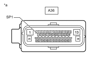
*a Front view of wire harness connector
(to Brake Actuator Assembly [Skid Control ECU])
Disconnect the brake actuator assembly (skid control ECU) connector.
-
Disconnect the brake booster with master cylinder assembly (skid control ECU) connector.
-
Measure the voltage according to the value(s) in the table below.
Standard Voltage Tester Connection Switch Condition Specified Condition A36-14 (SP1) - Body ground Engine switch on (IG) 11 to 14 V Result Proceed to OK NG
NG
CHECK HARNESS AND CONNECTOR (COMBINATION METER ASSEMBLY - BRAKE ACTUATOR ASSEMBLY [SKID CONTROL ECU]) Click here
OK
-
-
CHECK COMBINATION METER ASSEMBLY (INPUT WAVEFORM)
-
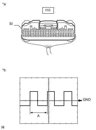
*a Component with harness connected
(Combination Meter Assembly)
*b Waveform Remove the combination meter assembly with the connector(s) still connected.
-
Connect an oscilloscope to terminal I10-20 (SI) and body ground.
-
Check the signal waveform according to the condition(s) in the table below.
Measurement Condition Item Condition Tester Connection I10-20 (SI) - Body ground Tool Setting 5 V/DIV., 20 ms./DIV. Vehicle Condition Driving at approximately 20 km/h (12 mph) Tech Tips
When the system is functioning normally, one wheel revolution generates 4 pulses. As the vehicle speed increases, the width indicated by A in the illustration narrows.
OK The waveform displayed is as shown in the illustration. Result Proceed to OK NG
OK 
REPLACE COMBINATION METER ASSEMBLY Click here
NG
REPLACE BRAKE ACTUATOR ASSEMBLY (SKID CONTROL ECU) Click here
-
-
CHECK HARNESS AND CONNECTOR (COMBINATION METER ASSEMBLY - STEREO COMPONENT AMPLIFIER ASSEMBLY)
-
*1: for 10.3 Inch Display
*2: for 8 Inch Display
*3: w/ Stereo Component Amplifier
*4: w/ Rain Sensor
*5: w/ Telematics System
*6: w/ Navigation System
-
Disconnect the combination meter assembly connector.
-
Disconnect the I152 radio receiver assembly connector.
-
Disconnect the P22*1 or P47*2 stereo component amplifier assembly connector.*3
-
Disconnect the I53 certification ECU (smart key ECU assembly) connector.
-
Disconnect the A35 ECM connector.
-
Disconnect the I56 windshield wiper relay assembly connector.*4
-
Disconnect the I40 telematics transceiver connector.*5
-
Disconnect the I160 navigationECU connector.*6
-
Measure the resistance according to the value(s) in the table below.
Standard Resistance for 10.3 Inch Display Tester Connection Condition Specified Condition I10-19 (+S) - P22-17 (SPD) Always Below 1 Ω I10-19 (+S) or P22-17 (SPD) - Body ground Always 10 kΩ or higher for 8 Inch Display Tester Connection Condition Specified Condition I10-19 (+S) - P47-11 (SPD) Always Below 1 Ω 47I10-19 (+S) or P47-11 (SPD) - Body ground Always 10 kΩ or higher Result Proceed to OK NG
OK
REPLACE STEREO COMPONENT AMPLIFIER ASSEMBLY Click here
NG
REPAIR OR REPLACE HARNESS OR CONNECTOR
-
-
CHECK HARNESS AND CONNECTOR (COMBINATION METER ASSEMBLY - WINDSHIELD WIPER RELAY ASSEMBLY)
-
*1: for 10.3 Inch Display
*2: for 8 Inch Display
*3: w/ Stereo Component Amplifier
*4: w/ Rain Sensor
*5: w/ Telematics System
*6: w/ Navigation System
-
Disconnect the combination meter assembly connector.
-
Disconnect the I152 radio receiver assembly connector.
-
Disconnect the P22*1 or P47*2 stereo component amplifier assembly connector.*3
-
Disconnect the I53 certification ECU (smart key ECU assembly) connector.
-
Disconnect the A35 ECM connector.
-
Disconnect the I56 windshield wiper relay assembly connector.*4
-
Disconnect the I40 telematics transceiver connector.*5
-
Disconnect the I160 navigationECU connector.*6
-
Measure the resistance according to the value(s) in the table below.
Standard Resistance Tester Connection Condition Specified Condition I10-19 (+S) - I56-24 (SPD) Always Below 1 Ω I10-19 (+S) or I56-24 (SPD) - Body ground Always 10 kΩ or higher Result Proceed to OK NG
OK
REPLACE WINDSHIELD WIPER RELAY ASSEMBLY Click here
NG
REPAIR OR REPLACE HARNESS OR CONNECTOR
-
-
CHECK HARNESS AND CONNECTOR (COMBINATION METER ASSEMBLY - NAVIGATION ECU)
-
*1: for 10.3 Inch Display
*2: for 8 Inch Display
*3: w/ Stereo Component Amplifier
*4: w/ Rain Sensor
-
Disconnect the combination meter assembly connector.
-
Disconnect the I152 radio receiver assembly connector.
-
Disconnect the P22*1 or P47*2 stereo component amplifier assembly connector.*3
-
Disconnect the I53 certification ECU (smart key ECU assembly) connector.
-
Disconnect the A35 ECM connector.
-
Disconnect the I56 windshield wiper relay assembly connector.*4
-
Disconnect the I40 telematics transceiver connector.
-
Disconnect the I160 navigationECU connector.
-
Measure the resistance according to the value(s) in the table below.
Standard Resistance Tester Connection Condition Specified Condition I10-19 (+S) - I160-9 (SPD) Always Below 1 Ω I10-19 (+S) or I160-9 (SPD) - Body ground Always 10 kΩ or higher Result Proceed to OK NG
OK
REPLACE NAVIGATION ECU Click here
NG
REPAIR OR REPLACE HARNESS OR CONNECTOR
-
-
CHECK HARNESS AND CONNECTOR (COMBINATION METER ASSEMBLY - BRAKE ACTUATOR ASSEMBLY [SKID CONTROL ECU])
-
Disconnect the I10 combination meter assembly connector.
-
Disconnect the A36 brake actuator assembly (skid control ECU) connector.
-
Measure the resistance according to the value(s) in the table below.
Standard Resistance Tester Connection Condition Specified Condition I10-20 (SI) - A36-14 (SP1) Always Below 1 Ω I10-20 (SI) or A36-14 (SP1) - Body ground Always 10 kΩ or higher Result Proceed to OK NG
OK
REPLACE COMBINATION METER ASSEMBLY Click here
NG
REPAIR OR REPLACE HARNESS OR CONNECTOR
-
-
CHECK HARNESS AND CONNECTOR (COMBINATION METER ASSEMBLY - CERTIFICATION ECU [SMART KEY ECU ASSEMBLY])
-
*1: for 10.3 Inch Display
*2: for 8 Inch Display
*3: w/ Stereo Component Amplifier
*4: w/ Rain Sensor
*5: w/ Telematics System
*6: w/ Navigation System
-
Disconnect the combination meter assembly connector.
-
Disconnect the I152 radio receiver assembly connector.
-
Disconnect the P22*1 or P47*2 stereo component amplifier assembly connector.*3
-
Disconnect the I53 certification ECU (smart key ECU assembly) connector.
-
Disconnect the A35 ECM connector.
-
Disconnect the I56 windshield wiper relay assembly connector.*4
-
Disconnect the I40 telematics transceiver connector.*5
-
Disconnect the I160 navigationECU connector.*6
-
Measure the resistance according to the value(s) in the table below.
Standard Resistance Tester Connection Condition Specified Condition I10-19 (+S) - I53-5 (SPD) Always Below 1 Ω I10-19 (+S) or I53-5 (SPD) - Body ground Always 10 kΩ or higher Result Proceed to OK NG
OK
REPLACE CERTIFICATION ECU (SMART KEY ECU ASSEMBLY)
NG
REPAIR OR REPLACE HARNESS OR CONNECTOR
-
-
CHECK HARNESS AND CONNECTOR (COMBINATION METER ASSEMBLY - ECM)
-
*1: for 10.3 Inch Display
*2: for 8 Inch Display
*3: w/ Stereo Component Amplifier
*4: w/ Rain Sensor
*5: w/ Telematics System
*6: w/ Navigation System
-
Disconnect the combination meter assembly connector.
-
Disconnect the I152 radio receiver assembly connector.
-
Disconnect the P22*1 or P47*2 stereo component amplifier assembly connector.*3
-
Disconnect the I53 certification ECU (smart key ECU assembly) connector.
-
Disconnect the A35 ECM connector.
-
Disconnect the I56 windshield wiper relay assembly connector.*4
-
Disconnect the I40 telematics transceiver connector.*5
-
Disconnect the I160 navigationECU connector.*6
-
Measure the resistance according to the value(s) in the table below.
Standard Resistance Tester Connection Condition Specified Condition I10-19 (+S) - A35-44 (SPD) Always Below 1 Ω I10-19 (+S) or A35-44 (SPD) - Body ground Always 10 kΩ or higher Result Result Proceed to OK (for 8AR-FTS) A OK (for 3ZR-FAE) B NG C
A
REPLACE ECM Click here
B
REPLACE ECM Click here
C
REPAIR OR REPLACE HARNESS OR CONNECTOR
-
-
CHECK HARNESS AND CONNECTOR (COMBINATION METER ASSEMBLY - TELEMATICS TRANSCEIVER)
-
*1: for 10.3 Inch Display
*2: for 8 Inch Display
*3: w/ Stereo Component Amplifier
*4: w/ Rain Sensor
*5: w/ Navigation System
-
Disconnect the combination meter assembly connector.
-
Disconnect the I152 radio receiver assembly connector.
-
Disconnect the P22*1 or P47*2 stereo component amplifier assembly connector.*3
-
Disconnect the I53 certification ECU (smart key ECU assembly) connector.
-
Disconnect the A35 ECM connector.
-
Disconnect the I56 windshield wiper relay assembly connector.*4
-
Disconnect the I40 telematics transceiver connector.
-
Disconnect the I160 navigationECU connector.*5
-
Measure the resistance according to the value(s) in the table below.
Standard Resistance Tester Connection Condition Specified Condition I10-19 (+S) - I40-10 (SPDP) Always Below 1 Ω I10-19 (+S) or I40-10 (SPDP) - Body ground Always 10 kΩ or higher Result Proceed to OK NG
OK
REPLACE TELEMATICS TRANSCEIVER Click here
NG
REPAIR OR REPLACE HARNESS OR CONNECTOR
-
-
CHECK HARNESS AND CONNECTOR (COMBINATION METER ASSEMBLY - RADIO RECEIVER ASSEMBLY)
-
*1: for 10.3 Inch Display
*2: for 8 Inch Display
*3: w/ Stereo Component Amplifier
*4: w/ Rain Sensor
*5: w/ Telematics System
*6: w/ Navigation System
-
Disconnect the combination meter assembly connector.
-
Disconnect the I152 radio receiver assembly connector.
-
Disconnect the P22*1 or P47*2 stereo component amplifier assembly connector.*3
-
Disconnect the I53 certification ECU (smart key ECU assembly) connector.
-
Disconnect the A35 ECM connector.
-
Disconnect the I56 windshield wiper relay assembly connector.*4
-
Disconnect the I40 telematics transceiver connector.*5
-
Disconnect the I160 navigationECU connector.*6
-
Measure the resistance according to the value(s) in the table below.
Standard Resistance Tester Connection Condition Specified Condition I10-19 (+S) - I152-27 (SPD) Always Below 1 Ω I10-19 (+S) or I152-27 (SPD) - Body ground Always 10 kΩ or higher Result Proceed to OK NG
OK
REPLACE RADIO RECEIVER ASSEMBLY Click here
NG
REPAIR OR REPLACE HARNESS OR CONNECTOR
-