LIGHTING SYSTEM Footwell Light Circuit
DESCRIPTION
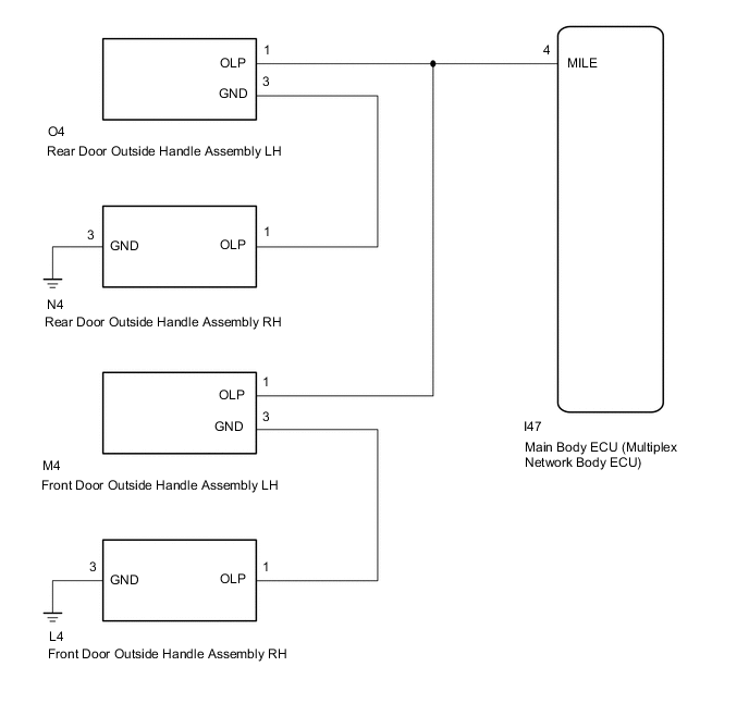
The main body ECU (multiplex network body ECU) controls the door outside handle foot lights.
WIRING DIAGRAM
PROCEDURE
-
PERFORM ACTIVE TEST USING GTS (EXTERIOR LIGHT)
-
Using the GTS, perform the Active Test.
Body Electrical > Main Body > Active TestTester Display Measurement Item Control Range Diagnostic Note Exterior Light Turns on the outside handle assembly (exterior foot light) ON or OFF -
Body Electrical > Main Body > Active TestTester Display Exterior Light OK Door mirror foot lights illuminate. Result Result Proceed to OK A NG (All outside handle foot lights do not illuminate) B NG (Front outside handle foot lights do not illuminate) C NG (Rear outside handle foot lights do not illuminate) D
A 
PROCEED TO NEXT SUSPECTED AREA SHOWN IN PROBLEM SYMPTOMS TABLE Click here
B
PROCEED TO NEXT SUSPECTED AREA SHOWN IN PROBLEM SYMPTOMS TABLE Click here
D 
CHECK REAR DOOR OUTSIDE HANDLE ASSEMBLY LH POWER SOURCE CIRCUIT Click here
C 
-
-
CHECK FRONT DOOR OUTSIDE HANDLE ASSEMBLY LH POWER SOURCE CIRCUIT
-
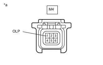
*a Front view of wire harness connector
(to Front Door Outside Handle Assembly LH)
Disconnect the front door outside handle assembly LH connector.
-
Measure the voltage according to the value(s) in the table below.
Standard Voltage Tester Connection Switch Condition Specified Condition M4-1 (OLP) - Body ground Engine switch on (IG) 11 to 14 V Result Proceed to OK NG
NG
REPAIR OR REPLACE HARNESS OR CONNECTOR
OK
-
-
INSPECT FRONT DOOR OUTSIDE HANDLE ASSEMBLY LH
-
Remove the front door outside handle assembly LH.
-
Inspect the front door outside handle assembly LH.
Result Proceed to OK NG
NG
REPLACE FRONT DOOR OUTSIDE HANDLE ASSEMBLY LH Click here
OK
-
-
INSPECT FRONT DOOR OUTSIDE HANDLE ASSEMBLY RH
-
Remove the front door outside handle assembly RH.
-
Inspect the front door outside handle assembly RH.
Result Proceed to OK NG
NG
REPLACE FRONT DOOR HANDLE ASSEMBLY OUTSIDE RH Click here
OK
-
-
CHECK HARNESS AND CONNECTOR (FRONT DOOR OUTSIDE HANDLE ASSEMBLY RH - BODY GROUND)
-
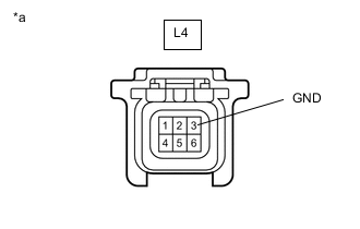
*a Front view of wire harness connector
(to Front Door Outside Handle Assembly RH)
Disconnect the front door outside handle assembly RH connector.
-
Measure the resistance according to the value(s) in the table below.
Standard Resistance Tester Connection Condition Specified Condition L4-3 (GND) - Body ground Always Below 1 Ω Result Proceed to OK NG
OK
REPAIR OR REPLACE HARNESS OR CONNECTOR (FRONT DOOR OUTSIDE HANDLE ASSEMBLY RH - FRONT DOOR OUTSIDE HANDLE ASSEMBLY LH)
NG
REPAIR OR REPLACE HARNESS OR CONNECTOR
-
-
CHECK REAR DOOR OUTSIDE HANDLE ASSEMBLY LH POWER SOURCE CIRCUIT
-
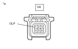
*a Front view of wire harness connector
(to Rear Door Outside Handle Assembly LH)
Disconnect the rear door outside handle assembly LH connector.
-
Measure the voltage according to the value(s) in the table below.
Standard Voltage Tester Connection Switch Condition Specified Condition O4-1 (OLP) - Body ground Engine switch on (IG) 11 to 14 V Result Proceed to OK NG
NG
REPAIR OR REPLACE HARNESS OR CONNECTOR
OK
-
-
INSPECT REAR DOOR OUTSIDE HANDLE ASSEMBLY LH
-
Remove the rear door outside handle assembly LH.
-
Inspect the rear door outside handle assembly LH.
Result Proceed to OK NG
NG
REPLACE REAR DOOR OUTSIDE HANDLE ASSEMBLY LH Click here
OK
-
-
INSPECT REAR DOOR OUTSIDE HANDLE ASSEMBLY RH
-
Remove the rear door outside handle assembly RH.
-
Inspect the rear door outside handle assembly RH.
Result Proceed to OK NG
NG
REPLACE REAR DOOR OUTSIDE HANDLE ASSEMBLY RH Click here
OK
-
-
CHECK HARNESS AND CONNECTOR (REAR DOOR OUTSIDE HANDLE ASSEMBLY RH - BODY GROUND)
-

*a Front view of wire harness connector
(to Rear Door Outside Handle Assembly RH)
Disconnect the rear door outside handle assembly RH connector.
-
Measure the resistance according to the value(s) in the table below.
Standard Resistance Tester Connection Condition Specified Condition N4-3 (GND) - Body ground Always Below 1 Ω Result Proceed to OK NG
OK
REPAIR OR REPLACE HARNESS OR CONNECTOR (REAR DOOR OUTSIDE HANDLE ASSEMBLY RH - REAR DOOR OUTSIDE HANDLE ASSEMBLY LH)
NG
REPAIR OR REPLACE HARNESS OR CONNECTOR
-