POWER DOOR LOCK CONTROL SYSTEM All Doors LOCK/UNLOCK Functions do not Operate Via Door Control Switch
DESCRIPTION
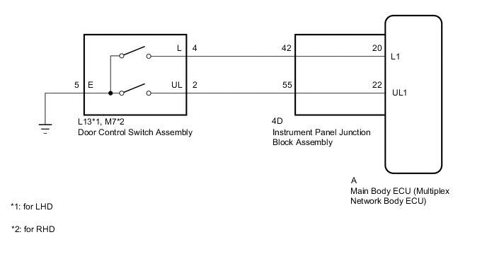
The main body ECU (multiplex network body ECU) receives switch signals from the door control switch assembly on the front passenger door and activates the door lock motor on each door according to these signals.
WIRING DIAGRAM
CAUTION / NOTICE / HINT
Note
-
When using the GTS with the vehicle engine switch off, connect the GTS to the DLC3 and turn a courtesy light switch on and off at intervals of 1.5 seconds or less until communication between the GTS and the vehicle begins. Then select Model Code "KEY REGIST" under manual mode and enter the following menus: Body Electrical / Entry&Start(CAN). While using the GTS, periodically turn a courtesy light switch on and off at intervals of 1.5 seconds or less to maintain communication between the GTS and the vehicle.
-
If the main body ECU (multiplex network body ECU) is replaced, refer to the Service Bulletin.
-
As the door control battery is installed between the vehicle battery and main body ECU (multiplex network body ECU), first perform the inspections in On-Vehicle Inspection to confirm that there are no malfunctions in the power source circuit for the main body ECU (multiplex network body ECU) before performing this troubleshooting procedure.*
*: w/ Door Control Battery
PROCEDURE
-
READ VALUE USING GTS (Door Lock SW-Lock, Door Lock SW-Unlock)
-
Connect the GTS to the DLC3.
-
Turn the engine switch on (IG).
-
Turn the GTS on.
-
Enter the following menus: Body Electrical / Main Body / Data List.
-
Read the Data List according to the display on the GTS.
Body Electrical > Main Body > Data ListTester Display Measurement Item Range Normal Condition Diagnostic Note Door Lock SW-Lock Door control switch assembly lock signal OFF or ON OFF: Lock side of door control switch assembly not pushed
ON: Lock side of door control switch assembly pushed
- Door Lock SW-Unlock Door control switch assembly unlock signal OFF or ON OFF: Unlock side of door control switch assembly not pushed
ON: Unlock side of door control switch assembly pushed
-
Body Electrical > Main Body > Data ListTester Display Door Lock SW-Lock Door Lock SW-Unlock OK The GTS indicates ON or OFF according to the switch operation shown in the table. Result Proceed to OK NG
OK 
REPLACE MAIN BODY ECU (MULTIPLEX NETWORK BODY ECU) for LHD: Click here for RHD: Click here
NG 
-
-
INSPECT DOOR CONTROL SWITCH ASSEMBLY
-
Remove the door control switch assembly.
-
Inspect the door control switch assembly.
Result Proceed to OK NG
NG
REPLACE DOOR CONTROL SWITCH ASSEMBLY Click here
OK
-
-
CHECK HARNESS AND CONNECTOR (DOOR CONTROL SWITCH ASSEMBLY - INSTRUMENT PANEL JUNCTION BLOCK ASSEMBLY AND BODY GROUND)
-
for LHD:
-
Disconnect the L13 door control switch assembly connector.
-
Disconnect the 4D instrument panel junction block assembly connector.
-
Measure the resistance according to the value(s) in the table below.
Standard Resistance Tester Connection Condition Specified Condition L13-4 (L) - 4D-42 Always Below 1 Ω L13-2 (UL) - 4D-55 Always Below 1 Ω L13-5 (E) - Body ground Always Below 1 Ω L13-4 (L) or 4D-42 - Body ground Always 10 kΩ or higher L13-2 (UL) or 4D-55 - Body ground Always 10 kΩ or higher
-
-
for RHD:
-
Disconnect the M7 door control switch assembly connector.
-
Disconnect the 4D instrument panel junction block assembly connector.
-
Measure the resistance according to the value(s) in the table below.
Standard Resistance Tester Connection Condition Specified Condition M7-4 (L) - 4D-42 Always Below 1 Ω M7-2 (UL) - 4D-55 Always Below 1 Ω M7-5 (E) - Body ground Always Below 1 Ω M7-4 (L) or 4D-42 - Body ground Always 10 kΩ or higher M7-2 (UL) or 4D-55 - Body ground Always 10 kΩ or higher
Result Proceed to OK NG -
NG
REPAIR OR REPLACE HARNESS OR CONNECTOR
OK
-
-
INSPECT INSTRUMENT PANEL JUNCTION BLOCK ASSEMBLY
-
Remove the instrument panel junction block assembly.
-
for LHD: Click here
-
for RHD: Click here
-
-
Remove the main body ECU (multiplex network body ECU) from the instrument panel junction block assembly.
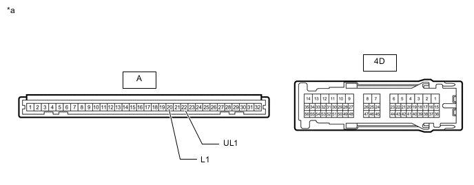
*a Component without harness connected
(Instrument Panel Junction Block Assembly)
- - -
Measure the resistance according to the value(s) in the table below.
Standard Resistance Tester Connection Condition Specified Condition A-20 (L1) - 4D-42 Always Below 1 Ω A-22 (UL1) - 4D-55 Always Below 1 Ω Result Proceed to OK NG
OK
REPLACE MAIN BODY ECU (MULTIPLEX NETWORK BODY ECU) for LHD: Click here for RHD: Click here
NG
REPLACE INSTRUMENT PANEL JUNCTION BLOCK ASSEMBLY for LHD: Click here for RHD: Click here
-