CAN COMMUNICATION SYSTEM(for RHD) Gateway ECU Communication Stop Mode
DESCRIPTION
| Detection Item | Symptom | Trouble Area |
|---|---|---|
| Gateway ECU Communication Stop Mode | Either condition is met:
|
|
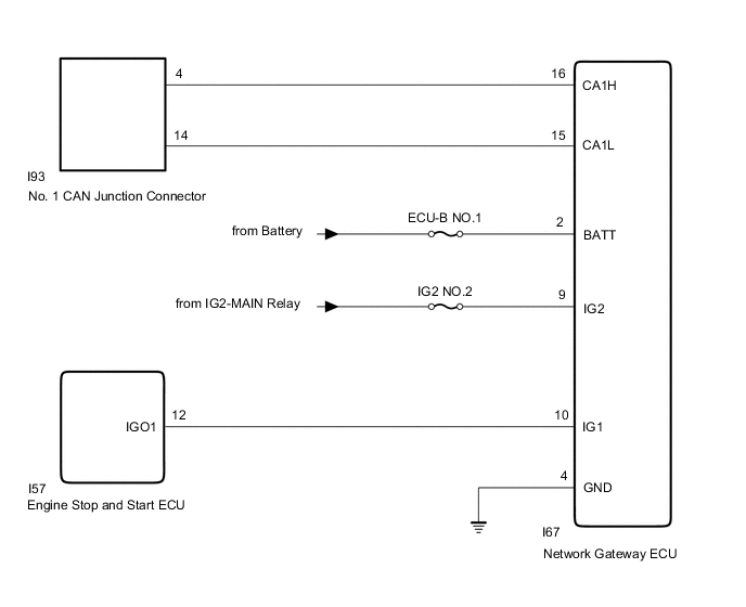
WIRING DIAGRAM
Figure 1. w/o Stop and Start System
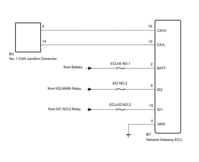
Figure 2. w/ Stop and Start System
CAUTION / NOTICE / HINT
Note
-
Before measuring the resistance of the CAN bus, turn the engine switch off and leave the vehicle for 1 minute or more without operating the key, switches or opening or closing the doors. After that, disconnect the cable from the negative (-) battery terminal and leave the vehicle for 1 minute or more before measuring the resistance.
-
After turning the engine switch off, waiting time may be required before disconnecting the cable from the negative (-) battery terminal. Therefore, make sure to read the disconnecting the cable from the negative (-) battery terminal notices before proceeding with work.
-
Because the order of diagnosis is important to allow correct diagnosis, make sure to begin troubleshooting using How to Proceed with Troubleshooting when CAN communication system related DTCs are output.
-
After performing repairs, perform the DTC check procedure and confirm that the DTCs are not output again.
-
DTC check procedure: Turn the engine switch on (IG) and wait at least 300 seconds, and then drive the vehicle at a speed of 36 km/h (22 mph) or more for 7 seconds or more.
-
After the repair, perform the CAN bus check and check that all the ECUs and sensors connected to the CAN communication system are displayed.
-
Inspect the fuses for circuits related to this system before performing the following procedure.
Tech Tips
-
Operating the engine switch, any other switches or a door triggers related ECU and sensor communication on the CAN. This communication will cause the resistance value to change.
-
Even after DTCs are cleared, if a DTC is stored again after driving the vehicle for a while, the malfunction may be occurring due to vibration of the vehicle. In such a case, wiggling the ECUs or wire harness while performing the inspection below may help determine the cause of the malfunction.
PROCEDURE
-
CHECK FOR OPEN IN CAN BUS WIRE (NETWORK GATEWAY ECU BRANCH WIRE)
-
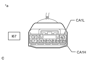
*a Front view of wire harness connector
(to Network Gateway ECU)
Disconnect the cable from the negative (-) battery terminal.
-
Disconnect the network gateway ECU connector.
-
Measure the resistance according to the value(s) in the table below.
Standard Resistance Tester Connection Condition Specified Value I67-16 (CA1H) - I67-15 (CA1L) Cable disconnected from negative (-) battery terminal 54 to 69 Ω Result Proceed to OK NG
NG 
REPAIR OR REPLACE CAN BRANCH WIRE OR CONNECTOR (NETWORK GATEWAY ECU)
OK 
-
-
CHECK HARNESS AND CONNECTOR (NETWORK GATEWAY ECU - BATTERY AND BODY GROUND)
-
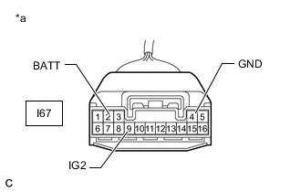
*a Front view of wire harness connector
(to Network Gateway ECU)
Reconnect the cable to the negative (-) battery terminal.
Note
When disconnecting the cable, some systems need to be initialized after the cable is reconnected.
-
Measure the voltage according to the value(s) in the table below.
Standard Voltage Tester Connection Condition Specified Condition I67-2 (BATT) - Body ground Always 11 to 14 V I67-9 (IG2) - Body ground Engine switch on (IG) 11 to 14 V -
Measure the resistance according to the value(s) in the table below.
Standard Resistance Tester Connection Condition Specified Condition I67-4 (GND) - Body ground Always Below 1 Ω Result Proceed to OK NG
NG
REPAIR OR REPLACE HARNESS OR CONNECTOR
OK
-
-
CHECK HARNESS AND CONNECTOR (NETWORK GATEWAY ECU - BATTERY)
-
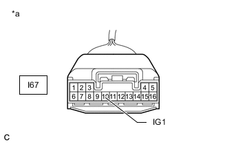
*a Front view of wire harness connector
(to Network Gateway ECU)
Measure the voltage according to the value(s) in the table below.
Standard Voltage w/o Stop and Start System Tester Connection Switch Condition Specified Condition I67-10 (IG1) - Body ground Engine switch on (IG) 11 to 14 V w/ Stop and Start System Tester Connection Switch Condition Specified Condition I67-10 (IG1) - Body ground Engine switch on (IG) 10.5 to 16 V Result Result Proceed to OK A NG (w/o Stop and Start System) B NG (w/ Stop and Start System) C
A
REPLACE NETWORK GATEWAY ECU Click here
B
REPAIR OR REPLACE HARNESS OR CONNECTOR
C
-
-
CHECK HARNESS AND CONNECTOR (NETWORK GATEWAY ECU - ENGINE STOP AND START ECU)
-
Disconnect the I57 engine stop and start ECU connector.
-
Measure the resistance according to the value(s) in the table below.
Standard Resistance Tester Connection Condition Specified Condition I67-10 (IG1) - I57-12 (IGO1) Always Below 1 Ω I67-10 (IG1) or I57-12 (IGO1) - Body ground Always 10 kΩ or higher Result Proceed to OK NG
OK
GO TO STOP AND START SYSTEM Click here
NG
REPAIR OR REPLACE HARNESS OR CONNECTOR
-