CAN COMMUNICATION SYSTEM Check Bus 2 Line for Short to +B
DESCRIPTION
There may be a short circuit between one of the CAN bus wire and +B when there is no resistance between terminal 18 (CA4H) of the central gateway ECU (network gateway ECU) and terminal 16 (BAT) of the DLC3, or terminal 17 (CA4L) of the central gateway ECU (network gateway ECU) and terminal 16 (BAT) of the DLC3.
| Symptom | Trouble Area |
|---|---|
| There is no resistance between terminal 18 (CA4H) of the central gateway ECU (network gateway ECU) and terminal 16 (BAT) of the DLC3, or terminal 17 (CA4L) of the central gateway ECU (network gateway ECU) and terminal 16 (BAT) of the DLC3. |
|
*2: w/ Headup Display
*3: w/ ASC System
*4: for AWD
WIRING DIAGRAM
-
for LHD:
-
for RHD:
CAUTION / NOTICE / HINT
CAUTION:
When performing the confirmation driving pattern, obey all speed limits and traffic laws.
Note
-
Because the order of diagnosis is important to allow correct diagnosis, make sure to begin troubleshooting using How to Proceed with Troubleshooting when CAN communication system related DTCs are output.
-
Before measuring the resistance of the CAN bus, turn the engine switch off and leave the vehicle for 1 minute or more without operating the key or any switches, or opening or closing the doors. After that, disconnect the cable from the negative (-) battery terminal and leave the vehicle for 1 minute or more before measuring the resistance.
-
After turning the engine switch off, waiting time may be required before disconnecting the cable from the negative (-) battery terminal. Therefore, make sure to read the disconnecting the cable from the negative (-) battery terminal notices before proceeding with work.
-
Some parts must be initialized and set when replacing or removing and installing parts.
-
After performing repairs, perform the DTC check procedure and confirm that the DTCs are not output again.
DTC check procedure: Turn the engine switch on (IG) and wait for 1 minute or more. Then operate the suspected malfunctioning system and drive the vehicle at 60 km/h (37 mph) or more for 5 minutes or more.
-
After the repair, perform the CAN bus check and check that all the ECUs and sensors connected to the CAN communication system are displayed as normal.
-
Before replacing the certification ECU (smart key ECU assembly), refer to Service Bulletin.
-
When replacing the combination meter assembly, always replace it with a new one. If a combination meter assembly which was installed to another vehicle is used, the information stored in it will not match the information from the vehicle and a DTC may be stored.
Tech Tips
-
Operating the engine switch, any switches or any doors triggers related ECU and sensor communication with the CAN, which causes resistance variation.
-
Even after DTCs are cleared, if a DTC is stored again after driving the vehicle for a while, the malfunction may be occurring due to vibration of the vehicle. In such a case, wiggling the ECUs or wire harness while performing the inspection below may help determine the cause of the malfunction.
PROCEDURE
-
CHECK FOR SHORT TO B+ IN CAN BUS WIRE (NO. 1 CAN JUNCTION CONNECTOR)
-
Disconnect the cable from the negative (-) battery terminal.
-
Disconnect the No. 1 CAN junction connector.

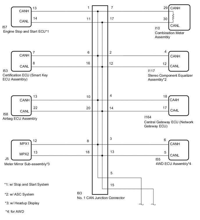
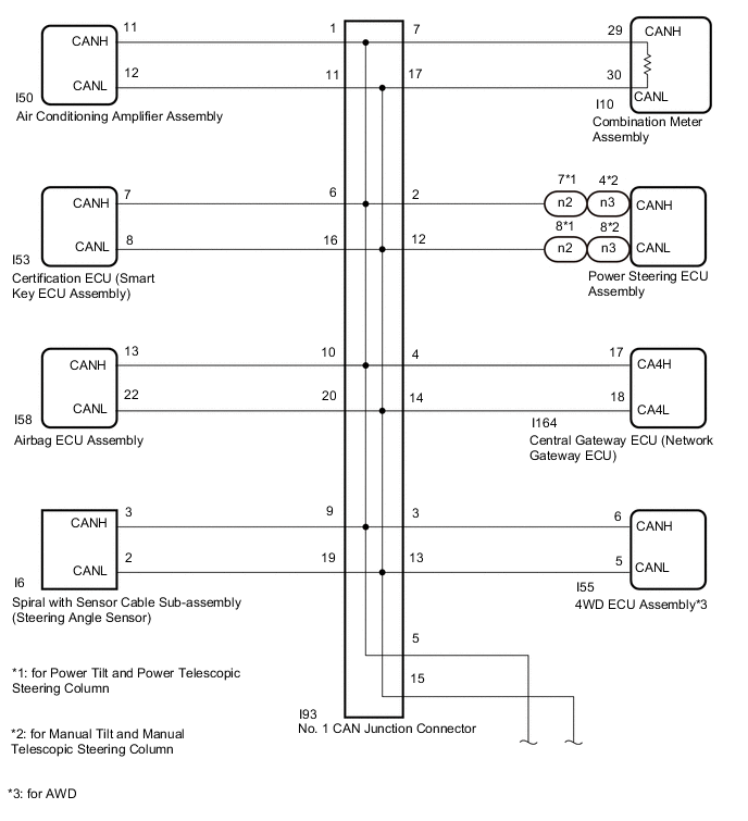
*a Front view of wire harness connector
(to No. 1 CAN Junction Connector)
*b
-
to Engine Stop and Start ECU (for LHD with Stop and Start System)
-
to Air Conditioning Amplifier Assembly (for RHD)
*c
-
to Stereo Component Equalizer Assembly (for LHD with ASC System)
-
to Power Steering ECU Assembly (for RHD)
*d to 4WD ECU Assembly (for AWD) *e to Central Gateway ECU (Network Gateway ECU) *f to No. 2 CAN Junction Connector *g to Certification ECU (Smart Key ECU Assembly) *h to Combination Meter Assembly *i to Meter Mirror Sub-assembly (for LHD with Headup Display) *j to Spiral with Sensor Cable Sub-assembly (Steering Angle Sensor) (for RHD) *k to Airbag ECU Assembly *l Front view of DLC3 -
-
Measure the resistance according to the value(s) in the table below.
Standard Resistance *1: for LHD with Stop and Start SystemTester Connection Condition Specified Condition Connected to I93-1 (CANH) - I7-16 (BAT) Cable disconnected from negative (-) battery terminal 6 kΩ or higher
-
Engine stop and start ECU*1
-
Air conditioning amplifier assembly*2
I93-11 (CANL) - I7-16 (BAT) I93-2 (CANH) - I7-16 (BAT) Cable disconnected from negative (-) battery terminal 6 kΩ or higher
-
Stereo component equalizer assembly*3
-
Power steering ECU assembly*2
I93-12 (CANL) - I7-16 (BAT) I93-3 (CANH) - I7-16 (BAT) Cable disconnected from negative (-) battery terminal 6 kΩ or higher 4WD ECU assembly*4 I93-13 (CANL) - I7-16 (BAT) I93-4 (CANH) - I7-16 (BAT) Cable disconnected from negative (-) battery terminal 6 kΩ or higher Central gateway ECU (network gateway ECU) I93-14 (CANL) - I7-16 (BAT) I93-5 (CANH) - I7-16 (BAT) Cable disconnected from negative (-) battery terminal 6 kΩ or higher No. 2 CAN junction connector I93-15 (CANL) - I7-16 (BAT) I93-6 (CANH) - I7-16 (BAT) Cable disconnected from negative (-) battery terminal 6 kΩ or higher Certification ECU (smart key ECU assembly) I93-16 (CANL) - I7-16 (BAT) I93-7 (CANH) - I7-16 (BAT) Cable disconnected from negative (-) battery terminal 6 kΩ or higher Combination meter assembly I93-17 (CANL) - I7-16 (BAT) I93-8 (CANH) - I7-16 (BAT) Cable disconnected from negative (-) battery terminal 6 kΩ or higher Meter mirror sub-assembly*5 I93-18 (CANL) - I7-16 (BAT) I93-9 (CANH) - I7-16 (BAT) Cable disconnected from negative (-) battery terminal 6 kΩ or higher Spiral with sensor cable sub-assembly (steering angle sensor)*2 I93-19 (CANL) - I7-16 (BAT) I93-10 (CANH) - I7-16 (BAT) Cable disconnected from negative (-) battery terminal 6 kΩ or higher Airbag ECU assembly I93-20 (CANL) - I7-16 (BAT)
*2: for RHD
*3: for LHD with ASC System
*4: for AWD
*5: for LHD with Headup Display
Result Result Proceed to OK A NG (Central gateway ECU [network gateway ECU] branch wire) B NG (No. 2 CAN junction connector CAN main wire) C NG (Wire to ECU or sensor) D -
A 
REPLACE NO. 1 CAN JUNCTION CONNECTOR
C 
CONNECT CONNECTOR Click here
D
GO TO STEP 6 Click here
B 
-
-
CONNECT CONNECTOR
-
Reconnect the I93 No. 1 CAN junction connector.
Result Proceed to NEXT
NEXT
-
-
CHECK FOR SHORT TO B+ IN CAN BUS WIRE (CENTRAL GATEWAY ECU [NETWORK GATEWAY ECU] - NO. 1 CAN JUNCTION CONNECTOR)
-
Disconnect the central gateway ECU (network gateway ECU) connector.
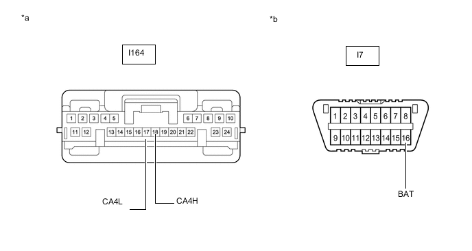
*a Front view of wire harness connector
(to Central Gateway ECU [Network Gateway ECU])
*b Front view of DLC3 -
Measure the resistance according to the value(s) in the table below.
Standard Resistance Tester Connection Condition Specified Condition I164-18 (CA4H) - I7-16 (BAT) Cable disconnected from negative (-) battery terminal 6 kΩ or higher I164-17 (CA4L) - I7-16 (BAT) Result Proceed to OK NG
OK
REPLACE CENTRAL GATEWAY ECU (NETWORK GATEWAY ECU) for LHD: Click here
REPLACE CENTRAL GATEWAY ECU (NETWORK GATEWAY ECU) for RHD: Click hereNG
REPAIR OR REPLACE CAN BRANCH LINE OR CONNECTOR (CENTRAL GATEWAY ECU [NETWORK GATEWAY ECU] - NO. 1 CAN JUNCTION CONNECTOR)
-
-
CONNECT CONNECTOR
-
Reconnect the I93 No. 1 CAN junction connector.
Result Proceed to NEXT
NEXT
-
-
CHECK FOR SHORT TO B+ IN CAN BUS WIRE (NO. 2 CAN JUNCTION CONNECTOR)
-
Disconnect the No. 2 CAN junction connector.
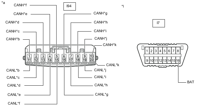
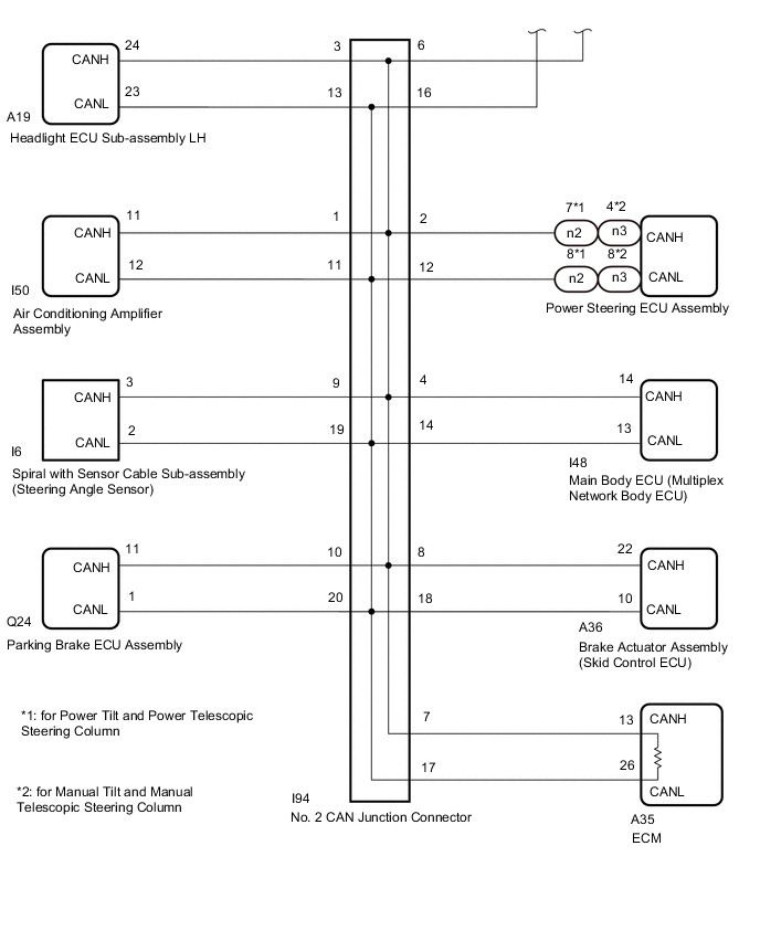
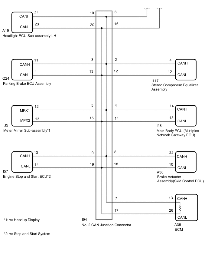
*a Front view of wire harness connector
(to No. 2 CAN Junction Connector)
*b to Air Conditioning Amplifier Assembly (for LHD) *c
-
to Power Steering ECU Assembly (for LHD)
-
to Stereo Component Equalizer Assembly (for RHD with ASC System)
*d
-
for Parking Brake ECU Assembly (for RHD)
-
for Headlight ECU Sub-assembly LH (for LHD)
*e to Main Body ECU (Multiplex Network Gateway ECU) *f to Meter Mirror Sub-assembly (for RHD with Headup Display) *g to No. 1 CAN Junction Connector *h to ECM *i to Brake Actuator Assembly *j
-
to Spiral with Sensor Cable Sub-assembly (Steering Angle Sensor) (for LHD)
-
to Engine Stop and Start ECU (for RHD with Stop and Start System)
*k
-
to Headlight ECU Sub-assembly LH (for RHD)
-
to Parking Brake ECU Assembly (for LHD)
*l Front view of DLC3 -
-
Measure the resistance according to the value(s) in the table below.
Standard Resistance *1: for LHDTester Connection Condition Specified Condition Connected to I94-1 (CANH) - I7-16 (BAT) Cable disconnected from negative (-) battery terminal 6 kΩ or higher Air conditioning amplifier assembly*1 I94-11 (CANL) - I7-16 (BAT) I94-2 (CANH) - I7-16 (BAT) Cable disconnected from negative (-) battery terminal 6 kΩ or higher
-
Power steering ECU assembly*1
-
Stereo component equalizer assembly*2
I94-12 (CANL) - I7-16 (BAT) I94-3 (CANH) - I7-16 (BAT) Cable disconnected from negative (-) battery terminal 6 kΩ or higher
-
Headlight ECU sub-assembly LH*1
-
Parking brake ECU assembly*2
I94-13 (CANL) - I7-16 (BAT) I94-4 (CANH) - I7-16 (BAT) Cable disconnected from negative (-) battery terminal 6 kΩ or higher Main body ECU (multiplex network gateway ECU) I94-14 (CANL) - I7-16 (BAT) I94-5 (CANH) - I7-16 (BAT) Cable disconnected from negative (-) battery terminal 6 kΩ or higher Meter mirror sub-assembly*3 I94-15 (CANL) - I7-16 (BAT) I94-6 (CANH) - I7-16 (BAT) Cable disconnected from negative (-) battery terminal 6 kΩ or higher No. 1 CAN junction connector I94-16 (CANL) - I7-16 (BAT) I94-7 (CANH) - I7-16 (BAT) Cable disconnected from negative (-) battery terminal 6 kΩ or higher ECM I94-17 (CANL) - I7-16 (BAT) I94-8 (CANH) - I7-16 (BAT) Cable disconnected from negative (-) battery terminal 6 kΩ or higher Brake actuator assembly I94-18 (CANL) - I7-16 (BAT) I94-9 (CANH) - I7-16 (BAT) Cable disconnected from negative (-) battery terminal 6 kΩ or higher
-
Spiral with sensor cable sub-assembly (steering angle sensor)*1
-
Engine stop and start ECU*4
I94-19 (CANL) - I7-16 (BAT) I94-10 (CANH) - I7-16 (BAT) Cable disconnected from negative (-) battery terminal 6 kΩ or higher
-
Parking brake ECU assembly*1
-
Headlight ECU sub-assembly LH*2
I94-20 (CANL) - I7-16 (BAT)
*2: for RHD
*3: for RHD with Headup Display
*4: for RHD with Stop and Start System
Result Result Proceed to OK A NG (No. 1 CAN junction connector CAN main wire) B NG (Wire to ECU or sensor) C -
A
REPLACE NO. 2 CAN JUNCTION CONNECTOR
B
REPAIR OR REPLACE CAN MAIN WIRE OR CONNECTOR (NO. 2 CAN JUNCTION CONNECTOR - NO. 1 CAN JUNCTION CONNECTOR)
C
-
-
CHECK FOR SHORT TO B+ IN CAN BUS WIRE (ECU, SENSOR)
-
Reconnect all wire harness connectors.
-
Disconnect the connector that includes terminals CANH and CANL from the ECU or sensor to which the bus line shorted to +B is connected.
-
Measure the resistance according to the value(s) in the table below.
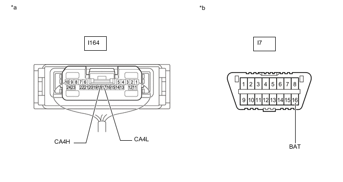
*a Component with harness connected
(Central Gateway ECU [Network Gateway ECU])
*b Front view of DLC3 Standard Resistance Tester Connection Condition Specified Condition I164-18 (CA4H) - I7-16 (BAT) Cable disconnected from negative (-) battery terminal 6 kΩ or higher I164-17 (CA4L) - I7-16 (BAT) Tech Tips
If the resistance changes to 6 kΩ or higher when the connector is disconnected from the ECU or sensor, there may be a short in the ECU or sensor.
Result Proceed to OK NG
OK
REPLACE CORRESPONDING ECU OR SENSOR
NG
REPAIR OR REPLACE CORRESPONDING ECU OR SENSOR BRANCH WIRE OR CONNECTOR
-