CAN COMMUNICATION SYSTEM(for LHD), Diagnostic DTC:U1002
| DTC Code | DTC Name |
|---|---|
| U1002 | Lost Communication with Gateway Module |
DESCRIPTION
-
The network gateway ECU stores this DTC when no signals can be received from the ECUs that have been memorized as those connected to the sub bus 2.
-
When the network gateway ECU receives a response signal from the ECUs connected to the sub bus 2, the network gateway ECU recognizes and memorizes that the ECU is connected to the sub bus 2. Based on this memorized data, the network gateway ECU monitors for malfunctions in the ECUs connected to the sub bus 2 when communicating with those ECUs. If the network gateway ECU cannot receive response signals from the ECUs that have been memorized as those connected to the sub bus 2, the network gateway ECU determines that a malfunction exists.
-
If 2 or more DTCs are output during the DTC check, one side of the CAN branch wire may be open (one side of the CANH [CAN branch wire]/CANL [CAN branch wire] of the ECU and/or sensor is open).
| DTC No. | Detection Item | DTC Detection Condition | Trouble Area | DTC Output from |
|---|---|---|---|---|
| U1002 | Lost Communication with Gateway Module | Lost communication with the gateway module. |
|
Network gateway ECU |
-
*1: w/ LEXUS Parking Assist-sensor System
-
*2: w/ Pre-crash Safety System
-
*3: w/ Lane Departure Alert System
-
*4: w/ Panoramic View Monitor System
-
*5: w/ Telematics Transceiver
-
*6: w/ Bus Buffer ECU
-
*7: w/ Blind Spot Monitor System
-
*8: w/ Adaptive Variable Suspension System
CAUTION / NOTICE / HINT
Note
-
Because the order of diagnosis is important to allow correct diagnosis, make sure to begin troubleshooting using How to Proceed with Troubleshooting when CAN communication system related DTCs are output.
-
Before measuring the resistance of the CAN bus, turn the engine switch off and leave the vehicle for 1 minute or more without operating the key, switches or opening or closing the doors. After that, disconnect the cable from the negative (-) battery terminal and leave the vehicle for 1 minute or more before measuring the resistance.
-
After turning the engine switch off, waiting time may be required before disconnecting the cable from the battery terminal. Therefore, make sure to read the disconnecting the cable from the battery terminal notice before proceeding with work.
-
DTC check procedure: Turn the engine switch on (IG) and wait at least 20 seconds.
-
After the repair, perform CAN Bus Check and check that all the ECUs and sensors connected to the CAN communication system are displayed.
-
When replacing the driving support ECU assembly, make sure to replace it with a new one.
-
When replacing the lane departure warning camera, make sure to replace it with a new one.
Tech Tips
-
Operating the engine switch, any other switches or a door triggers related ECU and sensor communication on the CAN. This communication will cause the resistance value to change.
-
Even after DTCs are cleared, if a DTC is stored again after driving the vehicle for a while, the malfunction may be occurring due to vibration of the vehicle. In such a case, wiggling the ECUs or wire harness while performing the inspection below may help determine the cause of the malfunction.
PROCEDURE
-
CHECK SUB BUS 2
-
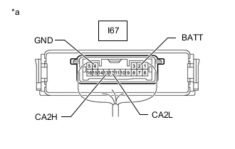
*a Component with harness connected
(Network Gateway ECU)
Disconnect the cable from the negative (-) battery terminal.
-
Measure the resistance according to the value(s) in the table below.
Standard Resistance Tester Connection Condition Specified Condition Resistance: Malfunction I67-13 (CA2H) - I67-12 (CA2L) Cable disconnected from negative (-) battery terminal 54 to 69 Ω Below 53 Ω: Short in CAN bus wire I67-13 (CA2H) - I67-12 (CA2L) Cable disconnected from negative (-) battery terminal 54 to 69 Ω Higher than 70 Ω: Open in CAN main wire I67-13 (CA2H) - I67-2 (BATT) Cable disconnected from negative (-) battery terminal 6 kΩ or higher Below 6 kΩ: +B short I67-12 (CA2L) - I67-2 (BATT) Cable disconnected from negative (-) battery terminal 6 kΩ or higher Below 6 kΩ: +B short I67-13 (CA2H) - I67-4 (GND) Cable disconnected from negative (-) battery terminal 200 Ω or higher Below 200 Ω: Ground short I67-12 (CA2L) - I67-4 (GND) Cable disconnected from negative (-) battery terminal 200 Ω or higher Below 200 Ω: Ground short Result Result Proceed to OK A NG
- Open in CAN main wire
B NG
- Short in CAN bus wire
C NG
- +B short
- Ground short
D
B 
CHECK FOR OPEN IN CAN BUS MAIN WIRE (NO. 3 CAN JUNCTION CONNECTOR) Click here
C
CHECK FOR SHORT IN CAN BUS WIRES (NO. 6 CAN JUNCTION CONNECTOR) Click here
D
CHECK FOR SHORT IN CAN BUS WIRES (NO. 6 CAN JUNCTION CONNECTOR) Click here
A 
-
-
CHECK HARNESS AND CONNECTOR (NETWORK GATEWAY ECU - BATTERY AND BODY GROUND)
-
*a Front view of wire harness connector
(to Network Gateway ECU)
Reconnect the cable to the negative (-) battery terminal.
Note
When disconnecting the cable, some systems need to be initialized after the cable is reconnected.
-
Measure the voltage according to the value(s) in the table below.
Standard Voltage Tester Connection Condition Specified Condition I67-2 (BATT) - Body ground Always 11 to 14 V I67-9 (IG2) - Body ground Engine switch on (IG) 11 to 14 V -
Measure the resistance according to the value(s) in the table below.
Standard Resistance Tester Connection Condition Specified Condition I67-4 (GND) - Body ground Always Below 1 Ω Result Proceed to OK NG
NG 
REPAIR OR REPLACE HARNESS OR CONNECTOR
OK
-
-
CHECK HARNESS AND CONNECTOR (NETWORK GATEWAY ECU - BATTERY)
-
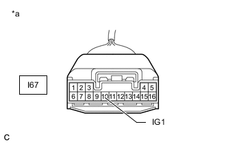
*a Front view of wire harness connector
(to Network Gateway ECU)
Measure the voltage according to the value(s) in the table below.
Standard Voltage w/o Stop and Start System Tester Connection Switch Condition Specified Condition I67-10 (IG1) - Body ground Engine switch on (IG) 11 to 14 V w/ Stop and Start System Tester Connection Switch Condition Specified Condition I67-10 (IG1) - Body ground Engine switch on (IG) 10.5 to 16 V Result Result Proceed to OK A NG (w/o Stop and Start System) B NG (w/ Stop and Start System) C
A
REPLACE NETWORK GATEWAY ECU Click here
B
REPAIR OR REPLACE HARNESS OR CONNECTOR
C
-
-
CHECK HARNESS AND CONNECTOR (NETWORK GATEWAY ECU - ENGINE STOP AND START ECU)
-
Disconnect the I57 engine stop and start ECU connector.
-
Measure the resistance according to the value(s) in the table below.
Standard Resistance Tester Connection Condition Specified Condition I67-10 (IG1) - I57-12 (IGO1) Always Below 1 Ω I67-10 (IG1) or I57-12 (IGO1) - Body ground Always 10 kΩ or higher Result Proceed to OK NG
OK
GO TO STOP AND START SYSTEM Click here
NG
REPAIR OR REPLACE HARNESS OR CONNECTOR
-
-
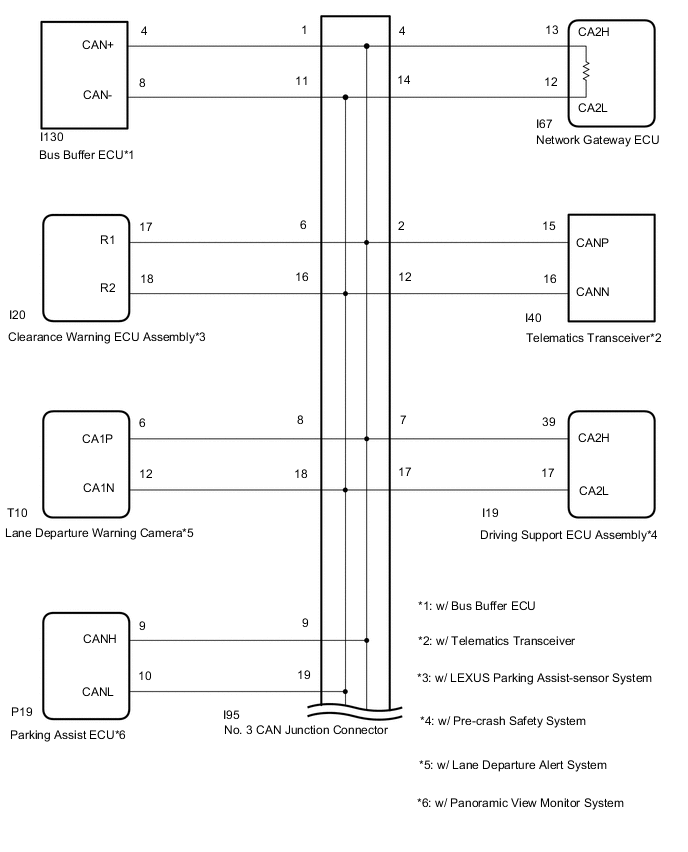
CHECK FOR OPEN IN CAN BUS MAIN WIRE (NO. 3 CAN JUNCTION CONNECTOR)
-
Disconnect the No. 3 CAN junction connector.
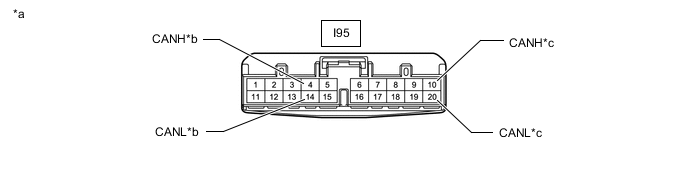
*a Front view of wire harness connector
(to No. 3 CAN Junction Connector)
*b to Network Gateway ECU *c to No. 6 CAN Junction Connector - - -
Measure the resistance according to the value(s) in the table below.
Standard Resistance Tester Connection Condition Specified Condition I95-4 (CANH) - I95-14 (CANL) Cable disconnected from negative (-) battery terminal 108 to 132 Ω I95-10 (CANH) - I95-20 (CANL) Cable disconnected from negative (-) battery terminal 108 to 132 Ω Result Result Proceed to OK A NG (to network gateway ECU CAN main wire) B NG (to No. 6 CAN junction connector CAN main wire) C
A
REPLACE NO. 3 CAN JUNCTION CONNECTOR
C
CONNECT CONNECTOR Click here
B
-
-
CONNECT CONNECTOR
-
Reconnect the No. 3 CAN junction connector.
Result Proceed to NEXT
NEXT
-
-
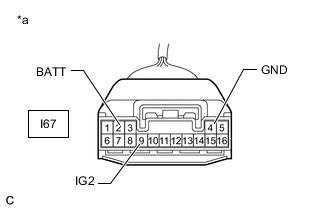
CHECK FOR OPEN IN CAN BUS MAIN WIRE (NETWORK GATEWAY ECU)
-
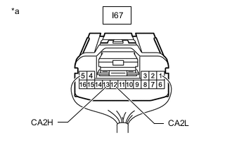
*a Rear view of wire harness connector
(to Network Gateway ECU)
Disconnect the network gateway ECU connector.
-
Measure the resistance according to the value(s) in the table below.
Standard Resistance Tester Connection Condition Specified Condition I67-13 (CA2H) - I67-12 (CA2L) Cable disconnected from negative (-) battery terminal 108 to 132 Ω Result Proceed to OK NG
OK
REPLACE NETWORK GATEWAY ECU Click here
NG
REPAIR OR REPLACE CAN MAIN WIRE OR CONNECTOR (NETWORK GATEWAY ECU - NO. 3 CAN JUNCTION CONNECTOR)
-
-
CONNECT CONNECTOR
-
Reconnect the No. 3 CAN junction connector.
Result Proceed to NEXT
NEXT
-
-
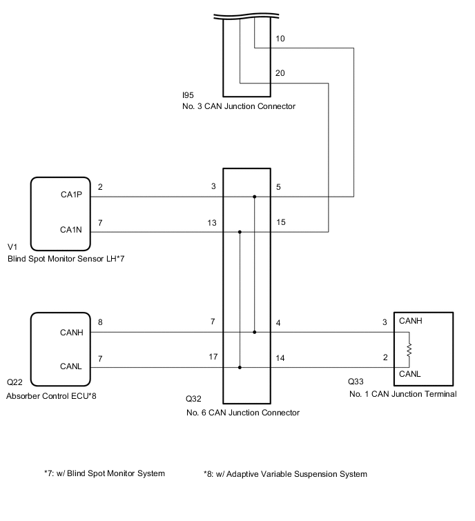
CHECK FOR OPEN IN CAN BUS MAIN WIRE (NO. 6 CAN JUNCTION CONNECTOR)
-
Disconnect the No. 6 CAN junction connector.
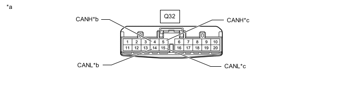
*a Front view of wire harness connector
(to No. 6 CAN Junction Connector)
*b to No. 1 CAN Junction Terminal *c to No. 3 CAN Junction Connector - - -
Measure the resistance according to the value(s) in the table below.
Standard Resistance Tester Connection Condition Specified Condition Q32-4 (CANH) - Q32-14 (CANL) Cable disconnected from negative (-) battery terminal 108 to 132 Ω Q32-5 (CANH) - Q32-15 (CANL) Cable disconnected from negative (-) battery terminal 108 to 132 Ω Result Result Proceed to OK A NG (to No. 1 CAN junction terminal CAN main wire) B NG (to No. 3 CAN junction connector CAN main wire) C
A
REPLACE NO. 6 CAN JUNCTION CONNECTOR
C
REPAIR OR REPLACE CAN MAIN WIRE OR CONNECTOR (NO. 6 CAN JUNCTION CONNECTOR - NO. 3 CAN JUNCTION CONNECTOR)
B
-
-
CONNECT CONNECTOR
-
Reconnect the No. 6 CAN junction connector.
Result Proceed to NEXT
NEXT
-
-
CHECK FOR OPEN IN CAN BUS MAIN WIRE (NO. 1 CAN JUNCTION TERMINAL)
-
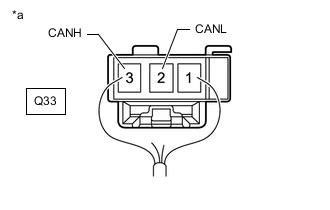
*a Rear view of wire harness connector
(to No. 1 CAN Junction Terminal)
Disconnect the No. 1 CAN junction terminal connector.
-
Measure the resistance according to the value(s) in the table below.
Standard Resistance Tester Connection Condition Specified Condition Q33-3 (CANH) - Q33-2 (CANL) Cable disconnected from negative (-) battery terminal 108 to 132 Ω Result Proceed to OK NG
OK
REPLACE NO. 1 CAN JUNCTION TERMINAL
NG
REPAIR OR REPLACE CAN MAIN WIRE OR CONNECTOR (NO. 1 CAN JUNCTION TERMINAL - NO. 6 CAN JUNCTION CONNECTOR)
-
-
CHECK FOR SHORT IN CAN BUS WIRES (NO. 6 CAN JUNCTION CONNECTOR)
-
*a Component with harness connected
(Network Gateway ECU)
Disconnect the Q32 No. 6 CAN junction connector.
-
Measure the resistance according to the value(s) in the table below.
Standard Resistance Tester Connection Condition Specified Condition I67-13 (CA2H) - I67-12 (CA2L) Cable disconnected from negative (-) battery terminal 108 to 132 Ω Result Proceed to OK NG
NG
CONNECT CONNECTOR Click here
OK
-
-
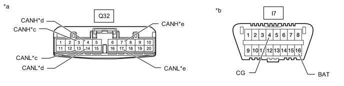
CHECK FOR SHORT IN CAN BUS WIRES (NO. 6 CAN JUNCTION CONNECTOR)
-
Measure the resistance according to the value(s) in the table below.
*a Front view of wire harness connector
(to No. 6 CAN Junction Connector)
*b to Blind Spot Monitor Sensor LH (w/ Blind Spot Monitor System) *c to No. 1 CAN Junction Terminal d to Absorber Control ECU (w/ Adaptive Variable Suspension System) Standard Resistance *1: w/ Blind Spot Monitor SystemTester Connection Condition Specified Condition Q32-3 (CANH) - Q32-13 (CANL)*1 Cable disconnected from negative (-) battery terminal 200 Ω or higher Q32-4 (CANH) - Q32-14 (CANL) Cable disconnected from negative (-) battery terminal 108 to 132 Ω Q32-7 (CANH) - Q32-17 (CANL)*2 Cable disconnected from negative (-) battery terminal 200 Ω or higher
*2: w/ Adaptive Variable Suspension System
Result Result Proceed to OK A NG (to blind spot monitor sensor LH CAN branch wire) (w/ Blind Spot Monitor System) B NG (to absorber control ECU CAN branch wire) (w/ Adaptive Variable Suspension System) C NG (to No. 1 CAN junction terminal CAN main wire) D
A
REPLACE NO. 6 CAN JUNCTION CONNECTOR
C
CONNECT CONNECTOR Click here
D
CONNECT CONNECTOR Click here
B
-
-
CONNECT CONNECTOR
-
Reconnect the No. 6 CAN junction connector.
Result Proceed to NEXT
NEXT
-
-
CHECK FOR SHORT IN CAN BUS WIRES (BLIND SPOT MONITOR SENSOR LH)
-
*a Front view of wire harness connector
(to Blind Spot Monitor Sensor LH)
Disconnect the blind spot monitor sensor LH connector.
-
Measure the resistance according to the value(s) in the table below.
Standard Resistance Tester Connection Condition Specified Condition V1-2 (CA1P) - V1-7 (CA1N) Cable disconnected from negative (-) battery terminal 54 to 69 Ω Result Proceed to OK NG
OK
REPLACE BLIND SPOT MONITOR SENSOR LH Click here
NG
REPAIR OR REPLACE CAN BRANCH WIRE CONNECTED TO BLIND SPOT MONITOR SENSOR LH (CA1P, CA1N)
-
-
CONNECT CONNECTOR
-
Reconnect the No. 6 CAN junction connector.
Result Proceed to NEXT
NEXT
-
-
CHECK FOR SHORT IN CAN BUS WIRES (ABSORBER CONTROL ECU)
-
*a Rear view of wire harness connector
(to Absorber Control ECU)
Disconnect the absorber control ECU connector.
-
Measure the resistance according to the value(s) in the table below.
Standard Resistance Tester Connection Condition Specified Condition Q22-8 (CANH) - Q22-7 (CANL) Cable disconnected from negative (-) battery terminal 54 to 69 Ω Result Proceed to OK NG
OK
REPLACE ABSORBER CONTROL ECU Click here
NG
REPAIR OR REPLACE CAN BRANCH WIRE CONNECTED TO ABSORBER CONTROL ECU (CANH, CANL)
-
-
CONNECT CONNECTOR
-
Reconnect the No. 6 CAN junction connector.
Result Proceed to NEXT
NEXT
-
-
CHECK FOR SHORT IN CAN BUS WIRES (NO. 1 CAN JUNCTION TERMINAL)
-
*a Rear view of wire harness connector
(to No. 1 CAN Junction Terminal)
Disconnect the No. 1 CAN junction terminal connector.
-
Measure the resistance according to the value(s) in the table below.
Standard Resistance Tester Connection Condition Specified Condition Q33-3 (CANH) - Q33-2 (CANL) Cable disconnected from negative (-) battery terminal 108 to 132 Ω Result Proceed to OK NG
OK
REPLACE NO. 1 CAN JUNCTION TERMINAL
NG
REPAIR OR REPLACE CAN MAIN WIRE OR CONNECTOR (NO. 1 CAN JUNCTION TERMINAL - NO. 6 CAN JUNCTION CONNECTOR)
-
-
CONNECT CONNECTOR
-
Reconnect the No. 6 CAN junction connector.
Result Proceed to NEXT
NEXT
-
-
CHECK FOR SHORT IN CAN BUS WIRES (NO. 3 CAN JUNCTION CONNECTOR)
-
Disconnect the No. 3 CAN junction connector.
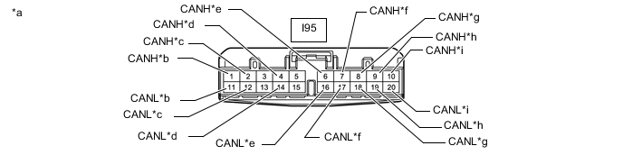
*a Front view of wire harness connector
(to No. 3 CAN Junction Connector)
*b to Bus Buffer ECU (w/ Bus Buffer ECU) *c to Telematics Transceiver (w/ Telematics Transceiver) *d to Network Gateway ECU *e to Clearance Warning ECU Assembly (w/ LEXUS Parking Assist-sensor System) *f to Driving Support ECU Assembly (w/ Pre-crash Safety System) *g to Lane Departure Warning Camera (w/ Lane Departure Alert System) *h to Parking Assist ECU (w/ Panoramic View Monitor System) *i to No. 6 CAN Junction Connector - - -
Measure the resistance according to the value(s) in the table below.
Standard Resistance *1: w/ Bus Buffer ECUTester Connection Condition Specified Condition I95-1 (CANH) - I95-11 (CANL)*1 Cable disconnected from negative (-) battery terminal 200 Ω or higher I95-2 (CANH) - I95-12 (CANL)*2 Cable disconnected from negative (-) battery terminal 200 Ω or higher I95-4 (CANH) - I95-14 (CANL) Cable disconnected from negative (-) battery terminal 108 to 132 Ω I95-6 (CANH) - I95-16 (CANL)*3 Cable disconnected from negative (-) battery terminal 200 Ω or higher I95-7 (CANH) - I95-17 (CANL)*4 Cable disconnected from negative (-) battery terminal 200 Ω or higher I95-8 (CANH) - I95-18 (CANL)*5 Cable disconnected from negative (-) battery terminal 200 Ω or higher I95-9 (CANH) - I95-19 (CANL)*6 Cable disconnected from negative (-) battery terminal 200 Ω or higher I95-10 (CANH) - I95-20 (CANL) Cable disconnected from negative (-) battery terminal 108 to 132 Ω
*2: w/ Telematics Transceiver
*3: w/ LEXUS Parking Assist-sensor System
*4: w/ Pre-crash Safety System
*5: w/ Lane Departure Alert System
*6: w/ Panoramic View Monitor System
Result Result Proceed to OK A NG (to bus buffer ECU CAN branch wire) (w/ Bus Buffer ECU) B NG (to telematics transceiver CAN branch wire) (w/ Telematics Transceiver) C NG (to network gateway ECU CAN main wire) D NG (to clearance warning ECU assembly CAN branch wire) (w/ LEXUS Parking Assist-sensor System) E NG (to driving support ECU assembly CAN branch wire) (w/ Pre-crash Safety System) F NG (to lane departure warning camera CAN branch wire) (w/ Lane Departure Alert System) G NG (to parking assist ECU CAN branch wire) (w/ Panoramic View Monitor System) H NG (to No. 6 CAN junction connector CAN main wire) I
A
REPLACE NO. 3 CAN JUNCTION CONNECTOR
C
CONNECT CONNECTOR Click here
D
CONNECT CONNECTOR Click here
E
CONNECT CONNECTOR Click here
F
CONNECT CONNECTOR Click here
G
CONNECT CONNECTOR Click here
H
CONNECT CONNECTOR Click here
I
REPAIR OR REPLACE CAN MAIN WIRE OR CONNECTOR (NO. 3 CAN JUNCTION CONNECTOR - NO. 6 CAN JUNCTION CONNECTOR)
B
-
-
CONNECT CONNECTOR
-
Reconnect the No. 3 CAN junction connector.
Result Proceed to NEXT
NEXT
-
-
CHECK FOR SHORT IN CAN BUS WIRES (BUS BUFFER ECU)
-
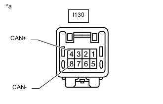
*a Front view of wire harness connector
(to Bus Buffer ECU)
Disconnect the bus buffer ECU connector.
-
Measure the resistance according to the value(s) in the table below.
Standard Resistance Tester Connection Condition Specified Condition I130-4 (CAN+) - I130-8 (CAN-) Cable disconnected from negative (-) battery terminal 54 to 69 Ω Result Proceed to OK NG
OK
REPLACE BUS BUFFER ECU
NG
REPAIR OR REPLACE CAN BRANCH WIRE CONNECTED TO BUS BUFFER ECU (CAN+, CAN-)
-
-
CONNECT CONNECTOR
-
Reconnect the No. 3 CAN junction connector.
Result Proceed to NEXT
NEXT
-
-
CHECK FOR SHORT IN CAN BUS WIRES (TELEMATICS TRANSCEIVER)
-
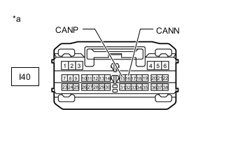
*a Front view of wire harness connector
(to Telematics Transceiver)
Disconnect the telematics transceiver connector.
-
Measure the resistance according to the value(s) in the table below.
Standard Resistance Tester Connection Condition Specified Condition I40-15 (CANP) - I40-16 (CANN) Cable disconnected from negative (-) battery terminal 54 to 69 Ω Result Proceed to OK NG
OK
REPLACE TELEMATICS TRANSCEIVER Click here
NG
REPAIR OR REPLACE CAN BRANCH WIRE CONNECTED TO TELEMATICS TRANSCEIVER (CANP, CANN)
-
-
CONNECT CONNECTOR
-
Reconnect the No. 3 CAN junction connector.
Result Proceed to NEXT
NEXT
-
-
CHECK FOR SHORT IN CAN BUS WIRES (NETWORK GATEWAY ECU)
-

*a Rear view of wire harness connector
(to Network Gateway ECU)
Disconnect the network gateway ECU connector.
-
Measure the resistance according to the value(s) in the table below.
Standard Resistance Tester Connection Condition Specified Condition I67-13 (CA2H) - I67-12 (CA2L) Cable disconnected from negative (-) battery terminal 108 to 132 Ω Result Proceed to OK NG
OK
REPLACE NETWORK GATEWAY ECU Click here
NG
REPAIR OR REPLACE CAN MAIN WIRE CONNECTED TO NETWORK GATEWAY ECU (CA2H, CA2L)
-
-
CONNECT CONNECTOR
-
Reconnect the No. 3 CAN junction connector.
Result Proceed to NEXT
NEXT
-
-
CHECK FOR SHORT IN CAN BUS WIRES (CLEARANCE WARNING ECU ASSEMBLY)
-
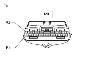
*a Rear view of wire harness connector
(to Clearance Warning ECU Assembly)
Disconnect the clearance warning ECU assembly connector.
-
Measure the resistance according to the value(s) in the table below.
Standard Resistance Tester Connection Condition Specified Condition I20-17 (R1) - I20-18 (R2) Cable disconnected from negative (-) battery terminal 54 to 69 Ω Result Proceed to OK NG
OK
REPLACE CLEARANCE WARNING ECU ASSEMBLY Click here
NG
REPAIR OR REPLACE CAN BRANCH WIRE CONNECTED TO CLEARANCE WARNING ECU ASSEMBLY (R1, R2)
-
-
CONNECT CONNECTOR
-
Reconnect the No. 3 CAN junction connector.
Result Proceed to NEXT
NEXT
-
-
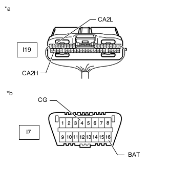
CHECK FOR SHORT IN CAN BUS WIRES (DRIVING SUPPORT ECU ASSEMBLY)
-
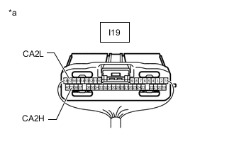
*a Rear view of wire harness connector
(to Driving Support ECU Assembly)
Disconnect the driving support ECU assembly connector.
-
Measure the resistance according to the value(s) in the table below.
Standard Resistance Tester Connection Condition Specified Condition I19-39 (CA2H) - I19-17 (CA2L) Cable disconnected from negative (-) battery terminal 54 to 69 Ω Result Proceed to OK NG
OK
REPLACE DRIVING SUPPORT ECU ASSEMBLY Click here
NG
REPAIR OR REPLACE CAN BRANCH WIRE CONNECTED TO DRIVING SUPPORT ECU ASSEMBLY (CA2H, CA2L)
-
-
CONNECT CONNECTOR
-
Reconnect the No. 3 CAN junction connector.
Result Proceed to NEXT
NEXT
-
-
CHECK FOR SHORT IN CAN BUS WIRES (LANE DEPARTURE WARNING CAMERA)
-
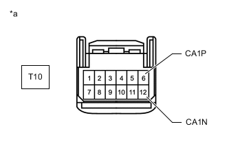
*a Front view of wire harness connector
(to Lane Departure Warning Camera)
Disconnect the lane departure warning camera connector.
-
Measure the resistance according to the value(s) in the table below.
Standard Resistance Tester Connection Condition Specified Condition T10-6 (CA1P) - T10-12 (CA1N) Cable disconnected from negative (-) battery terminal 54 to 69 Ω Result Proceed to OK NG
OK
REPLACE LANE DEPARTURE WARNING CAMERA Click here
NG
REPAIR OR REPLACE CAN BRANCH WIRE CONNECTED TO LANE DEPARTURE WARNING CAMERA (CA1P, CA1N)
-
-
CONNECT CONNECTOR
-
Reconnect the No. 3 CAN junction connector.
Result Proceed to NEXT
NEXT
-
-
CHECK FOR SHORT IN CAN BUS WIRES (PARKING ASSIST ECU)
-
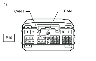
*a Front view of wire harness connector
(to Parking Assist ECU)
Disconnect the parking assist ECU connector.
-
Measure the resistance according to the value(s) in the table below.
Standard Resistance Tester Connection Condition Specified Condition P19-9 (CANH) - P19-10 (CANL) Cable disconnected from negative (-) battery terminal 54 to 69 Ω Result Proceed to OK NG
OK
REPLACE PARKING ASSIST ECU Click here
NG
REPAIR OR REPLACE CAN BRANCH WIRE CONNECTED TO PARKING ASSIST ECU (CANH, CANL)
-
-
CHECK FOR SHORT IN CAN BUS WIRES (NO. 6 CAN JUNCTION CONNECTOR)
-
*a Component with harness connected
(Network Gateway ECU)
Disconnect the Q32 No. 6 CAN junction connector.
-
Measure the resistance according to the value(s) in the table below.
Standard Resistance Tester Connection Condition Specified Condition I67-13 (CA2H) - I67-4 (GND) Cable disconnected from negative (-) battery terminal 200 Ω or higher I67-12 (CA2L) - I67-4 (GND) Cable disconnected from negative (-) battery terminal 200 Ω or higher I67-13 (CA2H) - I67-2 (BATT) Cable disconnected from negative (-) battery terminal 6 kΩ or higher I67-12 (CA2L) - I67-2 (BATT) Cable disconnected from negative (-) battery terminal 6 kΩ or higher Result Proceed to OK NG
NG
CONNECT CONNECTOR Click here
OK
-
-
CHECK FOR SHORT IN CAN BUS WIRES (NO. 6 CAN JUNCTION CONNECTOR)
-
Measure the resistance according to the value(s) in the table below.
*a Front view of wire harness connector
(to No. 6 CAN Junction Connector)
*b Front view of DLC3 *c to Blind Spot Monitor Sensor LH (w/ Blind Spot Monitor System) *d to No. 1 CAN Junction Terminal *e to Absorber Control ECU (w/ Adaptive Variable Suspension System) - - Standard Resistance *1: w/ Blind Spot Monitor SystemTester Connection Condition Specified Condition Q32-3 (CANH) - I7-4 (CG)*1 Cable disconnected from negative (-) battery terminal 200 Ω or higher Q32-13 (CANL) - I7-4 (CG)*1 Cable disconnected from negative (-) battery terminal 200 Ω or higher Q32-3 (CANH) - I7-16 (BAT)*1 Cable disconnected from negative (-) battery terminal 6 kΩ or higher Q32-13 (CANL) - I7-16 (BAT)*1 Cable disconnected from negative (-) battery terminal 6 kΩ or higher Q32-4 (CANH) - I7-4 (CG) Cable disconnected from negative (-) battery terminal 200 Ω or higher Q32-14 (CANL) - I7-4 (CG) Cable disconnected from negative (-) battery terminal 200 Ω or higher Q32-4 (CANH) - I7-16 (BAT) Cable disconnected from negative (-) battery terminal 6 kΩ or higher Q32-14 (CANL) - I7-16 (BAT) Cable disconnected from negative (-) battery terminal 6 kΩ or higher Q32-7 (CANH) - I7-4 (CG)*2 Cable disconnected from negative (-) battery terminal 200 Ω or higher Q32-17 (CANL) - I7-4 (CG)*2 Cable disconnected from negative (-) battery terminal 200 Ω or higher Q32-7 (CANH) - I7-16 (BAT)*2 Cable disconnected from negative (-) battery terminal 6 kΩ or higher Q32-17 (CANL) - I7-16 (BAT)*2 Cable disconnected from negative (-) battery terminal 6 kΩ or higher
*2: w/ Adaptive Variable Suspension System
Result Result Proceed to OK A NG (to blind spot monitor sensor LH CAN branch wire) (w/ Blind Spot Monitor System) B NG (to absorber control ECU CAN branch wire) (w/ Adaptive Variable Suspension System) C NG (to No. 1 CAN junction terminal CAN main wire) D
A
REPLACE NO. 6 CAN JUNCTION CONNECTOR
C
CONNECT CONNECTOR Click here
D
CONNECT CONNECTOR Click here
B
-
-
CONNECT CONNECTOR
-
Reconnect the No. 6 CAN junction connector.
Result Proceed to NEXT
NEXT
-
-
CHECK FOR SHORT IN CAN BUS WIRES (BLIND SPOT MONITOR SENSOR LH)
-
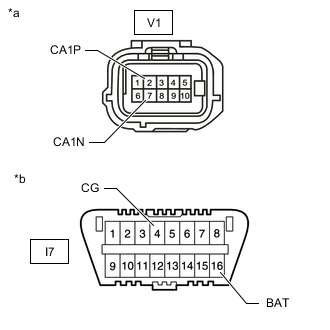
*a Front view of wire harness connector
(to Blind Spot Monitor Sensor LH)
*b Front view of DLC3 Disconnect the blind spot monitor sensor LH connector.
-
Measure the resistance according to the value(s) in the table below.
Standard Resistance Tester Connection Condition Specified Condition V1-2 (CA1P) - I7-4 (CG) Cable disconnected from negative (-) battery terminal 200 Ω or higher V1-7 (CA1N) - I7-4 (CG) Cable disconnected from negative (-) battery terminal 200 Ω or higher V1-2 (CA1P) - I7-16 (BAT) Cable disconnected from negative (-) battery terminal 6 kΩ or higher V1-7 (CA1N) - I7-16 (BAT) Cable disconnected from negative (-) battery terminal 6 kΩ or higher Result Proceed to OK NG
OK
REPLACE BLIND SPOT MONITOR SENSOR LH Click here
NG
REPAIR OR REPLACE CAN BRANCH WIRE CONNECTED TO BLIND SPOT MONITOR SENSOR LH (CA1P, CA1N)
-
-
CONNECT CONNECTOR
-
Reconnect the No. 6 CAN junction connector.
Result Proceed to NEXT
NEXT
-
-
CHECK FOR SHORT IN CAN BUS WIRES (ABSORBER CONTROL ECU)
-
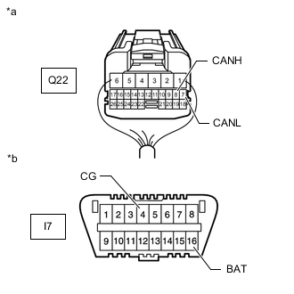
*a Rear view of wire harness connector
(to Absorber Control ECU)
*b Front view of DLC3 Disconnect the absorber control ECU connector.
-
Measure the resistance according to the value(s) in the table below.
Standard Resistance Tester Connection Condition Specified Condition Q22-8 (CANH) - I7-4 (CG) Cable disconnected from negative (-) battery terminal 200 Ω or higher Q22-7 (CANL) - I7-4 (CG) Cable disconnected from negative (-) battery terminal 200 Ω or higher Q22-8 (CANH) - I7-16 (BAT) Cable disconnected from negative (-) battery terminal 6 kΩ or higher Q22-7 (CANL) - I7-16 (BAT) Cable disconnected from negative (-) battery terminal 6 kΩ or higher Result Proceed to OK NG
OK
REPLACE ABSORBER CONTROL ECU Click here
NG
REPAIR OR REPLACE CAN BRANCH WIRE CONNECTED TO ABSORBER CONTROL ECU (CANH, CANL)
-
-
CONNECT CONNECTOR
-
Reconnect the No. 6 CAN junction connector.
Result Proceed to NEXT
NEXT
-
-
CHECK FOR SHORT IN CAN BUS WIRES (NO. 1 CAN JUNCTION TERMINAL)
-
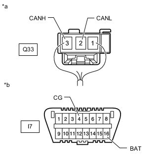
*a Rear view of wire harness connector
(to No. 1 CAN Junction Terminal)
*b Front view of DLC3 Disconnect the No. 1 CAN junction terminal connector.
-
Measure the resistance according to the value(s) in the table below.
Standard Resistance Tester Connection Condition Specified Condition Q33-3 (CANH) - I7-4 (CG) Cable disconnected from negative (-) battery terminal 200 Ω or higher Q33-2 (CANL) - I7-4 (CG) Cable disconnected from negative (-) battery terminal 200 Ω or higher Q33-3 (CANH) - I7-16 (BAT) Cable disconnected from negative (-) battery terminal 6 kΩ or higher Q33-2 (CANL) - I7-16 (BAT) Cable disconnected from negative (-) battery terminal 6 kΩ or higher Result Proceed to OK NG
OK
REPLACE NO. 1 CAN JUNCTION TERMINAL
NG
REPAIR OR REPLACE CAN MAIN WIRE OR CONNECTOR (NO. 1 CAN JUNCTION TERMINAL - NO. 8 CAN JUNCTION CONNECTOR)
-
-
CONNECT CONNECTOR
-
Reconnect the No. 6 CAN junction connector.
Result Proceed to NEXT
NEXT
-
-
CHECK FOR SHORT IN CAN BUS WIRES (NO. 3 CAN JUNCTION CONNECTOR)
-
Disconnect the No. 3 CAN junction connector.
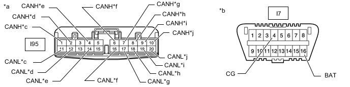
*a Front view of wire harness connector
(to No. 3 CAN Junction Connector)
*b Front view of DLC3 *c to Bus Buffer ECU (w/ Bus Buffer ECU) *d to Telematics Transceiver (w/ Telematics Transceiver) *e to Network Gateway ECU *f to Clearance Warning ECU Assembly (w/ LEXUS Parking Assist-sensor System) *g to Driving Support ECU Assembly (w/ Pre-crash Safety System) *h to Lane Departure Warning Camera (w/ Lane Departure Alert System) *i to Parking Assist ECU (w/ Panoramic View Monitor System) *j to No. 6 CAN Junction Connector -
Measure the resistance according to the value(s) in the table below.
Standard Resistance *1: w/ Bus Buffer ECUTester Connection Condition Specified Condition I95-1 (CANH) - I7-4 (CG)*1 Cable disconnected from negative (-) battery terminal 200 Ω or higher I95-11 (CANL) - I7-4 (CG)*1 Cable disconnected from negative (-) battery terminal 200 Ω or higher I95-1 (CANH) - I7-16 (BAT)*1 Cable disconnected from negative (-) battery terminal 6 kΩ or higher I95-11 (CANL) - I7-16 (BAT)*1 Cable disconnected from negative (-) battery terminal 6 kΩ or higher I95-2 (CANH) - I7-4 (CG)*2 Cable disconnected from negative (-) battery terminal 200 Ω or higher I95-12 (CANL) - I7-4 (CG)*2 Cable disconnected from negative (-) battery terminal 200 Ω or higher I95-2 (CANH) - I7-16 (BAT)*2 Cable disconnected from negative (-) battery terminal 6 kΩ or higher I95-12 (CANL) - I7-16 (BAT)*2 Cable disconnected from negative (-) battery terminal 6 kΩ or higher I95-4 (CANH) - I7-4 (CG) Cable disconnected from negative (-) battery terminal 200 Ω or higher I95-14 (CANL) - I7-4 (CG) Cable disconnected from negative (-) battery terminal 200 Ω or higher I95-4 (CANH) - I7-16 (BAT) Cable disconnected from negative (-) battery terminal 6 kΩ or higher I95-14 (CANL) - I7-16 (BAT) Cable disconnected from negative (-) battery terminal 6 kΩ or higher I95-6 (CANH) - I7-4 (CG)*3 Cable disconnected from negative (-) battery terminal 200 Ω or higher I95-16 (CANL) - I7-4 (CG)*3 Cable disconnected from negative (-) battery terminal 200 Ω or higher I95-6 (CANH) - I7-16 (BAT)*3 Cable disconnected from negative (-) battery terminal 6 kΩ or higher I95-16 (CANL) - I7-16 (BAT)*3 Cable disconnected from negative (-) battery terminal 6 kΩ or higher I95-7 (CANH) - I7-4 (CG)*4 Cable disconnected from negative (-) battery terminal 200 Ω or higher I95-17 (CANL) - I7-4 (CG)*4 Cable disconnected from negative (-) battery terminal 200 Ω or higher I95-7 (CANH) - I7-16 (BAT)*4 Cable disconnected from negative (-) battery terminal 6 kΩ or higher I95-17 (CANL) - I7-16 (BAT)*4 Cable disconnected from negative (-) battery terminal 6 kΩ or higher I95-8 (CANH) - I7-4 (CG)*5 Cable disconnected from negative (-) battery terminal 200 Ω or higher I95-18 (CANL) - I7-4 (CG)*5 Cable disconnected from negative (-) battery terminal 200 Ω or higher I95-8 (CANH) - I7-16 (BAT)*5 Cable disconnected from negative (-) battery terminal 6 kΩ or higher I95-18 (CANL) - I7-16 (BAT)*5 Cable disconnected from negative (-) battery terminal 6 kΩ or higher I95-9 (CANH) - I7-4 (CG)*6 Cable disconnected from negative (-) battery terminal 200 Ω or higher I95-19 (CANL) - I7-4 (CG)*6 Cable disconnected from negative (-) battery terminal 200 Ω or higher I95-9 (CANH) - I7-16 (BAT)*6 Cable disconnected from negative (-) battery terminal 6 kΩ or higher I95-19 (CANL) - I7-16 (BAT)*6 Cable disconnected from negative (-) battery terminal 6 kΩ or higher I95-10 (CANH) - I7-4 (CG) Cable disconnected from negative (-) battery terminal 200 Ω or higher I95-20 (CANL) - I7-4 (CG) Cable disconnected from negative (-) battery terminal 200 Ω or higher I95-10 (CANH) - I7-16 (BAT) Cable disconnected from negative (-) battery terminal 6 kΩ or higher I95-20 (CANL) - I7-16 (BAT) Cable disconnected from negative (-) battery terminal 6 kΩ or higher
*2: w/ Telematics Transceiver
*3: w/ LEXUS Parking Assist-sensor System
*4: w/ Pre-crash Safety System
*5: w/ Lane Departure Alert System
*6: w/ Panoramic View Monitor System
Result Result Proceed to OK A NG (to bus buffer ECU CAN branch wire) (w/ Bus Buffer ECU) B NG (to telematics transceiver CAN branch wire) (w/ Telematics Transceiver) C NG (to network gateway ECU CAN main wire) D NG (to clearance warning ECU assembly CAN branch wire) (w/ LEXUS Parking Assist-sensor System) E NG (to driving support ECU assembly CAN branch wire) (w/ Pre-crash Safety System) F NG (to lane departure warning camera CAN branch wire) (w/ Lane Departure Alert System) G NG (to parking assist ECU CAN branch wire) (w/ Panoramic View Monitor System) H NG (to No. 6 CAN junction connector CAN main wire) I
A
REPLACE NO. 4 CAN JUNCTION CONNECTOR
C
CONNECT CONNECTOR Click here
D
CONNECT CONNECTOR Click here
E
CONNECT CONNECTOR Click here
F
CONNECT CONNECTOR Click here
G
CONNECT CONNECTOR Click here
H
CONNECT CONNECTOR Click here
I
REPAIR OR REPLACE CAN MAIN WIRE OR CONNECTOR (NO. 3 CAN JUNCTION CONNECTOR - NO. 6 CAN JUNCTION CONNECTOR)
B
-
-
CONNECT CONNECTOR
-
Reconnect the No. 3 CAN junction connector.
Result Proceed to NEXT
NEXT
-
-
CHECK FOR SHORT IN CAN BUS WIRES (BUS BUFFER ECU)
-
*a Front view of wire harness connector
(to Bus Buffer ECU)
*b Front view of DLC3 Disconnect the bus buffer ECU connector.
-
Measure the resistance according to the value(s) in the table below.
Standard Resistance Tester Connection Condition Specified Condition I130-4 (CAN+) - I7-4 (CG) Cable disconnected from negative (-) battery terminal 200 Ω or higher I130-8 (CAN-) - I7-4 (CG) Cable disconnected from negative (-) battery terminal 200 Ω or higher I130-4 (CAN+) - I7-16 (BAT) Cable disconnected from negative (-) battery terminal 6 kΩ or higher I130-8 (CAN-) - I7-16 (BAT) Cable disconnected from negative (-) battery terminal 6 kΩ or higher Result Proceed to OK NG
OK
REPLACE BUS BUFFER ECU
NG
REPAIR OR REPLACE CAN BRANCH WIRE CONNECTED TO BUS BUFFER ECU (CAN+, CAN-)
-
-
CONNECT CONNECTOR
-
Reconnect the No. 3 CAN junction connector.
Result Proceed to NEXT
NEXT
-
-
CHECK FOR SHORT IN CAN BUS WIRES (TELEMATICS TRANSCEIVER)
-
*a Front view of wire harness connector
(to Telematics Transceiver)
*b Front view of DLC3 Disconnect the telematics transceiver connector.
-
Measure the resistance according to the value(s) in the table below.
Standard Resistance Tester Connection Condition Specified Condition I40-15 (CANP) - I7-4 (CG) Cable disconnected from negative (-) battery terminal 200 Ω or higher I40-16 (CANN) - I7-4 (CG) Cable disconnected from negative (-) battery terminal 200 Ω or higher I40-15 (CANP) - I7-16 (BAT) Cable disconnected from negative (-) battery terminal 6 kΩ or higher I40-16 (CANN) - I7-16 (BAT) Cable disconnected from negative (-) battery terminal 6 kΩ or higher Result Proceed to OK NG
OK
REPLACE TELEMATICS TRANSCEIVER Click here
NG
REPAIR OR REPLACE CAN BRANCH WIRE CONNECTED TO TELEMATICS TRANSCEIVER (CANP, CANN)
-
-
CONNECT CONNECTOR
-
Reconnect the No. 3 CAN junction connector.
Result Proceed to NEXT
NEXT
-
-
CHECK FOR SHORT IN CAN BUS WIRES (NETWORK GATEWAY ECU)
-
*a Rear view of wire harness connector
(to Network Gateway ECU)
*b Front view of DLC3 Disconnect the network gateway ECU connector.
-
Measure the resistance according to the value(s) in the table below.
Standard Resistance Tester Connection Condition Specified Condition I67-13 (CA2H) - I7-4 (CG) Cable disconnected from negative (-) battery terminal 200 Ω or higher I67-12 (CA2L) - I7-4 (CG) Cable disconnected from negative (-) battery terminal 200 Ω or higher I67-13 (CA2H) - I7-16 (BAT) Cable disconnected from negative (-) battery terminal 6 kΩ or higher I67-12 (CA2L) - I7-16 (BAT) Cable disconnected from negative (-) battery terminal 6 kΩ or higher Result Proceed to OK NG
OK
REPLACE NETWORK GATEWAY ECU Click here
NG
REPAIR OR REPLACE CAN MAIN WIRE CONNECTED TO NETWORK GATEWAY ECU (CA2H, CA2L)
-
-
CONNECT CONNECTOR
-
Reconnect the No. 3 CAN junction connector.
Result Proceed to NEXT
NEXT
-
-
CHECK FOR SHORT IN CAN BUS WIRES (CLEARANCE WARNING ECU ASSEMBLY)
-
*a Rear view of wire harness connector
(to Clearance Warning ECU Assembly)
*b Front view of DLC3 Disconnect the clearance warning ECU assembly connector.
-
Measure the resistance according to the value(s) in the table below.
Standard Resistance Tester Connection Condition Specified Condition I20-17 (R1) - I7-4 (CG) Cable disconnected from negative (-) battery terminal 200 Ω or higher I20-18 (R2) - I7-4 (CG) Cable disconnected from negative (-) battery terminal 200 Ω or higher I20-17 (R1) - I7-16 (BAT) Cable disconnected from negative (-) battery terminal 6 kΩ or higher I20-18 (R2) - I7-16 (BAT) Cable disconnected from negative (-) battery terminal 6 kΩ or higher Result Proceed to OK NG
OK
REPLACE CLEARANCE WARNING ECU ASSEMBLY Click here
NG
REPAIR OR REPLACE CAN BRANCH WIRE CONNECTED TO CLEARANCE WARNING ECU ASSEMBLY (R1, R2)
-
-
CONNECT CONNECTOR
-
Reconnect the No. 3 CAN junction connector.
Result Proceed to NEXT
NEXT
-
-
CHECK FOR SHORT IN CAN BUS WIRES (DRIVING SUPPORT ECU ASSEMBLY)
-
*a Rear view of wire harness connector
(to Driving Support ECU Assembly)
*b Front view of DLC3 Disconnect the driving support ECU assembly connector.
-
Measure the resistance according to the value(s) in the table below.
Standard Resistance Tester Connection Condition Specified Condition I19-39 (CA2H) - I7-4 (CG) Cable disconnected from negative (-) battery terminal 200 Ω or higher I19-17 (CA2L) - I7-4 (CG) Cable disconnected from negative (-) battery terminal 200 Ω or higher I19-39 (CA2H) - I7-16 (BAT) Cable disconnected from negative (-) battery terminal 6 kΩ or higher I19-17 (CA2L) - I7-16 (BAT) Cable disconnected from negative (-) battery terminal 6 kΩ or higher Result Proceed to OK NG
OK
REPLACE DRIVING SUPPORT ECU ASSEMBLY Click here
NG
REPAIR OR REPLACE CAN BRANCH WIRE CONNECTED TO DRIVING SUPPORT ECU ASSEMBLY (CA2H, CA2L)
-
-
CONNECT CONNECTOR
-
Reconnect the No. 3 CAN junction connector.
Result Proceed to NEXT
NEXT
-
-
CHECK FOR SHORT IN CAN BUS WIRES (LANE DEPARTURE WARNING CAMERA)
-
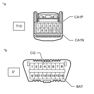
*a Front view of wire harness connector
(to Lane Departure Warning Camera)
*b Front view of DLC3 Disconnect the lane departure warning camera connector.
-
Measure the resistance according to the value(s) in the table below.
Standard Resistance Tester Connection Condition Specified Condition T10-6 (CA1P) - I7-4 (CG) Cable disconnected from negative (-) battery terminal 200 Ω or higher T10-12 (CA1N) - I7-4 (CG) Cable disconnected from negative (-) battery terminal 200 Ω or higher T10-6 (CA1P) - I7-16 (BAT) Cable disconnected from negative (-) battery terminal 6 kΩ or higher T10-12 (CA1N) - I7-16 (BAT) Cable disconnected from negative (-) battery terminal 6 kΩ or higher Result Proceed to OK NG
OK
REPLACE LANE DEPARTURE WARNING CAMERA Click here
NG
REPAIR OR REPLACE CAN BRANCH WIRE CONNECTED TO LANE DEPARTURE WARNING CAMERA (CA1P, CA1N)
-
-
CONNECT CONNECTOR
-
Reconnect the No. 3 CAN junction connector.
Result Proceed to NEXT
NEXT
-
-
CHECK FOR SHORT IN CAN BUS WIRES (PARKING ASSIST ECU)
-
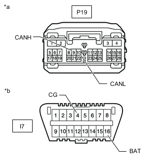
*a Front view of wire harness connector
(to Parking Assist ECU)
*b Front view of DLC3 Disconnect the parking assist ECU connector.
-
Measure the resistance according to the value(s) in the table below.
Standard Resistance Tester Connection Condition Specified Condition P19-9 (CANH) - I7-4 (CG) Cable disconnected from negative (-) battery terminal 200 Ω or higher P19-10 (CANL) - I7-4 (CG) Cable disconnected from negative (-) battery terminal 200 Ω or higher P19-9 (CANH) - I7-16 (BAT) Cable disconnected from negative (-) battery terminal 6 kΩ or higher P19-10 (CANL) - I7-16 (BAT) Cable disconnected from negative (-) battery terminal 6 kΩ or higher Result Proceed to OK NG
OK
REPLACE PARKING ASSIST ECU Click here
NG
REPAIR OR REPLACE CAN BRANCH WIRE CONNECTED TO PARKING ASSIST ECU (CANH, CANL)
-