LIN COMMUNICATION SYSTEM TERMINALS OF ECU
-
CHECK INSTRUMENT PANEL JUNCTION BLOCK ASSEMBLY AND MAIN BODY ECU (MULTIPLEX NETWORK BODY ECU)
-
Remove the main body ECU (multiplex network body ECU).
-
for LHD:
-
for RHD:
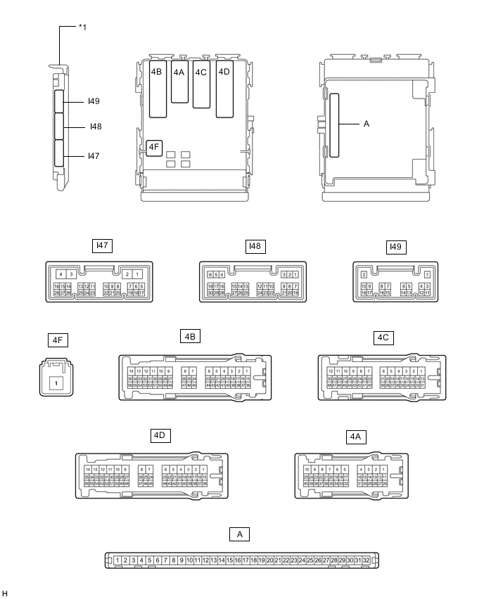
*1 Main Body ECU (Multiplex Network Body ECU) - - -
-
Connect the instrument panel junction block assembly connectors.
-
Measure the voltage and resistance according to the value(s) in the table below.
Tech Tips
Measure the values on the wire harness side with the connectors disconnected.
Tester Connection Wiring Color Terminal Description Condition Specified Condition A-11 (GND1) - Body ground - Ground Always Below 1 Ω A-31 (BECU) - Body ground - Battery power supply Always 11 to 14 V A-30 (ACC) - Body ground - ACC power supply Engine switch on (ACC) 11 to 14 V A-30 (ACC) - Body ground - ACC power supply Engine switch off Below 1 V A-32 (IG) - Body ground - IG power supply Engine switch on (IG) 11 to 14 V A-32 (IG) - Body ground - IG power supply Engine switch off Below 1 V
-
-
CHECK MULTIPLEX NETWORK MASTER SWITCH ASSEMBLY
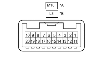
*A for LHD *B for RHD
-
Disconnect the M10*1 or L3*2 multiplex network master switch assembly connector.
*1: for LHD
*2: for RHD
-
Measure the resistance and voltage according to the value(s) in the table below.
for LHD Terminal No. (Symbol) Wiring Color Terminal Description Condition Specified Condition M10-11 (B) - Body ground SB - Body ground Battery power supply Always 11 to 14 V M10-12 (GND) - Body ground W-B - Body ground Ground Always Below 1 Ω for RHD Terminal No. (Symbol) Wiring Color Terminal Description Condition Specified Condition L3-11 (B) - Body ground L - Body ground Battery power supply Always 11 to 14 V L3-12 (GND) - Body ground W-B - Body ground Ground Always Below 1 Ω
-
-
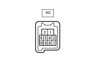
CHECK FRONT POWER WINDOW REGULATOR MOTOR ASSEMBLY LH
-
Disconnect the M2 front power window regulator motor assembly LH connector.
-
Measure the resistance and voltage according to the value(s) in the table below.
Terminal No. (Symbol) Wiring Color Terminal Description Condition Specified Condition M2-2 (B) - Body ground P - Body ground (for LHD)
W - Body ground (for RHD)
Battery power supply Always 11 to 14 V M2-1 (GND) - Body ground W-B - Body ground Ground Always Below 1 Ω
-
-
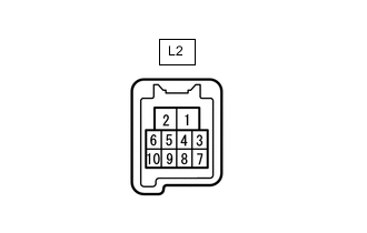
CHECK FRONT POWER WINDOW REGULATOR MOTOR ASSEMBLY RH
-
Disconnect the L2 front power window regulator motor assembly RH connector.
-
Measure the resistance and voltage according to the value(s) in the table below.
Terminal No. (Symbol) Wiring Color Terminal Description Condition Specified Condition L2-2 (B) - Body ground G - Body ground Battery power supply Always 11 to 14 V L2-1 (GND) - Body ground W-B - Body ground Ground Always Below 1 Ω
-
-
CHECK REAR POWER WINDOW REGULATOR MOTOR ASSEMBLY LH
-
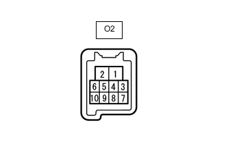
Disconnect the O2 rear power window regulator motor assembly LH connector.
-
Measure the resistance and voltage according to the value(s) in the table below.
Terminal No. (Symbol) Wiring Color Terminal Description Condition Specified Condition O2-2 (B) - Body ground LA-Y - Body ground Battery power supply Always 11 to 14 V O2-1 (GND) - Body ground W-B - Body ground Ground Always Below 1 Ω
-
-
CHECK REAR POWER WINDOW REGULATOR MOTOR ASSEMBLY RH
-
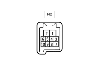
Disconnect the N2 rear power window regulator motor assembly RH connector.
-
Measure the resistance and voltage according to the value(s) in the table below.
Terminal No. (Symbol) Wiring Color Terminal Description Condition Specified Condition N2-2 (B) - Body ground LA-G - Body ground Battery power supply Always 11 to 14 V N2-1 (GND) - Body ground W-B - Body ground Ground Always Below 1 Ω
-
-
CHECK SLIDING ROOF DRIVE GEAR SUB-ASSEMBLY (w/ Sliding Roof System or Roof Sunshade System)
-
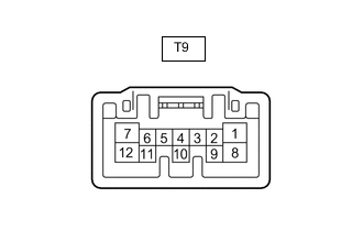
Disconnect the T9 sliding roof drive gear sub-assembly connector.
-
Measure the resistance and voltage according to the value(s) in the table below.
Terminal No. (Symbol) Wiring Color Terminal Description Condition Specified Condition T9-8 (B) - Body ground W - Body ground Battery power supply Always 11 to 14 V T9-12 (E) - Body ground W-B - Body ground Ground Always Below 1 Ω
-
-
CHECK CERTIFICATION ECU (SMART KEY ECU ASSEMBLY)
-
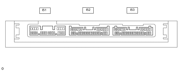
Disconnect the I53 certification ECU connector.
-
Measure the resistance and voltage according to the value(s) in the table below.
Terminal No. (Symbol) Wiring Color Terminal Description Condition Specified Condition I53-10 (+B) - Body ground W - Body ground Battery power supply Always 11 to 14 V I53-11 (E) - Body ground W-B - Body ground Ground Always Below 1 Ω
-
-
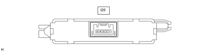
CHECK ID CODE BOX (IMMOBILISER CODE BOX)
-
Disconnect the I26 ID code box connector.
-
Measure the resistance and voltage according to the value(s) in the table below.
Terminal No. (Symbol) Wiring Color Terminal Description Condition Specified Condition I26-1 (+B) - Body ground B - Body ground Battery power supply Always 11 to 14 V I26-5 (GND) - Body ground W-B - Body ground Ground Always Below 1 Ω
-
-
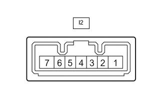
CHECK STEERING LOCK ACTUATOR ASSEMBLY
-
Disconnect the I2 steering lock actuator assembly connector.
-
Measure the resistance and voltage according to the value(s) in the table below.
Terminal No. (Symbol) Wiring Color Terminal Description Condition Specified Condition I2-7 (B) - Body ground L - Body ground Battery power supply Always 11 to 14 V I2-1 (GND) - Body ground W-B - Body ground Ground Always Below 1 Ω
-
-
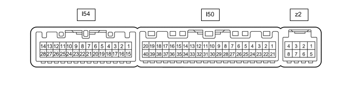
CHECK AIR CONDITIONING AMPLIFIER ASSEMBLY
-
Disconnect the I50 air conditioning amplifier assembly connector.
-
Measure the resistance and voltage according to the value(s) in the table below.
Terminal No. (Symbol) Wiring Color Terminal Description Condition Specified Condition I50-1 (IG+) - Body ground SB - Body ground IG power supply Engine switch off Below 1 V I50-1 (IG+) - Body ground SB - Body ground IG power supply Engine switch on (IG) 11 to 14 V I50-21 (B) - Body ground GR - Body ground Battery power supply Always 11 to 14 V I50-14 (GND) - Body ground W-B - Body ground Ground Always Below 1 Ω
-
-
CHECK AIR CONDITIONING CONTROL ASSEMBLY

-
Disconnect the I13 air conditioning control assembly connector.
-
Measure the resistance and voltage according to the value(s) in the table below.
w/o Stop and Start System Terminal No. (Symbol) Wiring Color Terminal Description Condition Specified Condition I13-8 (IG+) - Body ground LG - Body ground IG power supply Engine switch on (IG) 11 to 14 V I13-8 (IG+) - Body ground LG - Body ground IG power supply Engine switch off Below 1 V I13-14 (GND) - Body ground W-B - Body ground Ground Always Below 1 Ω w/ Stop and Start System Terminal No. (Symbol) Wiring Color Terminal Description Condition Specified Condition I13-8 (IG+) - Body ground W - Body ground IG power supply Engine switch on (IG) 10.5 to 16 V I13-8 (IG+) - Body ground W - Body ground IG power supply Engine switch off Below 1 V I13-14 (GND) - Body ground W-B - Body ground Ground Always Below 1 Ω
-
-
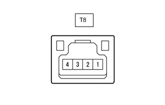
CHECK RAIN SENSOR (w/ Rain Sensor)
-
Disconnect the T8 rain sensor connector.
-
Measure the resistance and voltage according to the value(s) in the table below.
Terminal No. (Symbol) Wiring Color Terminal Description Condition Specified Condition T8-4 (SIG) - Body ground GR - Body ground IG power supply Engine switch on (IG) 11 to 14 V T8-4 (SIG) - Body ground GR - Body ground IG power supply Engine switch off Below 1 V T8-2 (ES) - Body ground W - Body ground Ground circuit Always Below 1 Ω
-
-
CHECK WINDSHIELD WIPER RELAY ASSEMBLY (w/ Rain Sensor)
-
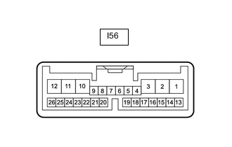
Disconnect the I56 windshield wiper relay assembly connector.
-
Measure the resistance and voltage according to the value(s) in the table below.
Terminal No. (Symbol) Wiring Color Terminal Description Condition Specified Condition I56-2 (IG) - Body ground L - Body ground IG power supply Engine switch on (IG) 11 to 14 V I56-2 (IG) - Body ground L - Body ground IG power supply Engine switch off Below 1 V I56-12 (E) - Body ground W-B - Body ground Ground Always Below 1 Ω I56-16 (WIG) - Body ground L - Body ground Battery power supply Engine switch on (IG) 11 to 14 V Engine switch off Below 1 V
-
-
CHECK DOUBLE LOCK DOOR CONTROL RELAY ASSEMBLY (w/Double Locking System)
-
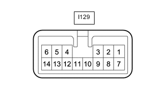
Disconnect the I129 double lock door control relay assembly connector.
-
Measure the resistance and voltage according to the value(s) in the table below.
Terminal No. (Symbol) Wiring Color Terminal Description Condition Specified Condition I129-7 (CPUB) - Body ground L - Body ground Battery power supply Engine switch off 11 to 14 V I129-1 (+B) - Body ground G - Body ground Battery power supply Always 11 to 14 V I129-14 (GND) - Body ground W-B - Body ground Ground Always Below 1 Ω
-
-
CHECK HEADLIGHT LIGHT CONTROL ECU SUB-ASSEMBLY LH

-
Disconnect the A19 headlight light control ECU sub-assembly LH connector.
-
Measure the resistance and voltage according to the value(s) in the table below.
Terminal No. (Symbol) Wiring Color Terminal Description Condition Specified Condition A19-4 (IG) - Body ground L - Body ground IG power supply Engine switch off Below 1 V Engine switch on (IG) 11 to 14 V A19-13 (ECUB) - Body ground R - Body ground Battery power supply Engine switch off Below 1 V Engine switch on (IG) 11 to 14 V A19-12 (GND) - Body ground W-B - Body ground Ground Always Below 1 Ω
-
-
CHECK HEADLIGHT LIGHT CONTROL ECU SUB-ASSEMBLY RH
-
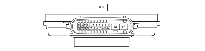
Disconnect the A20 headlight light control ECU sub-assembly RH connector.
-
Measure the resistance and voltage according to the value(s) in the table below.
Terminal No. (Symbol) Wiring Color Terminal Description Condition Specified Condition A20-4 (IG) - Body ground G - Body ground IG power supply Engine switch off Below 1 V Engine switch on (IG) 11 to 14 V A20-13 (ECUB) - Body ground B - Body ground Battery power supply Engine switch off Below 1 V Engine switch on (IG) 11 to 14 V A20-12 (GND) - Body ground W-B - Body ground Ground Always Below 1 Ω
-