MAIN BODY ECU(for LHD) REMOVAL
PROCEDURE
-
PRECAUTION
Note
After turning the engine switch off, waiting time may be required before disconnecting the cable from the negative (-) battery terminal. Therefore, make sure to read the disconnecting the cable from the negative (-) battery terminal notice before proceeding with work.
-
DISCONNECT CABLE FROM NEGATIVE BATTERY TERMINAL (w/o Pretensioner)
Note
When disconnecting the cable, some systems need to be initialized after the cable is reconnected.
-
DISCHARGE DOOR CONTROL BATTERY AND DISCONNECT CABLE FROM NEGATIVE BATTERY TERMINAL (w/ Rear Pretensioner)
Note
-
Make sure to perform this procedure with the power supply of the battery and door control battery cut to prevent damage during removal and installation of the instrument panel junction block assembly.
-
Make sure to perform the following procedures, and then perform removal and installation of the instrument panel junction block assembly with the power supply from the battery and door control battery cut.
-
When disconnecting the cable, some systems need to be initialized after the cable is reconnected.
Tech Tips
-
When the engine switch is turned off after the door control battery is fully charged, the door control battery becomes completely discharged due to self-discharge within approximately 30 minutes.
-
Approximately 90 seconds after the engine switch is turned on (IG), the door control battery becomes fully charged.
-
When approximately 30 minutes or more elapse after the engine switch is turned off, the Active Test may not be able to be performed.
-
Turn the engine switch off.
-
Connect the GTS to the DLC3.
-
Turn the GTS on.
-
Enter the following menus: Body Electrical / Main Body / Active Test.
Body Electrical > Main Body > Active TestTester Display Control Range Shock Detection Unlock ON/OFF Note
Do not perform the Active Test at this time.
-
Disconnect the cable from the negative (-) battery terminal.
-
Repeat the "Shock Detection Unlock" Active Test until the multiplex network body ECU (main body ECU) communication lost error "Lost communication with vehicle" appears on the GTS display.
Body Electrical > Main Body > Active TestTester Display Shock Detection Unlock Tech Tips
-
When the door control battery becomes completely discharged and the power supply is cut, the multiplex network body ECU (main body ECU) communication lost error "Lost communication with vehicle" appears on the GTS display.
-
The number of times the Active Test can be performed depends on the charge condition of the door control battery.
-
-
-
REMOVE DOOR SCUFF PLATE ASSEMBLY LH
-
REMOVE COWL SIDE TRIM BOARD LH
-
REMOVE INSTRUMENT SIDE PANEL LH
-
REMOVE NO. 1 INSTRUMENT PANEL SAFETY PAD SUB-ASSEMBLY
-
REMOVE REAR CONSOLE ARMREST ASSEMBLY
-
REMOVE UPPER NO. 2 CONSOLE PANEL GARNISH
-
REMOVE NO. 1 INSTRUMENT PANEL UNDER COVER SUB-ASSEMBLY
-
REMOVE LOWER NO. 1 INSTRUMENT PANEL FINISH PANEL
-
REMOVE INSTRUMENT PANEL JUNCTION BLOCK ASSEMBLY
-
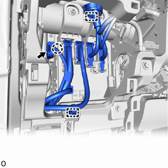
Disconnect the connector.
-
Detach the claw and disconnect the connector housing.
-
Detach the 2 wire harness clamps.
-
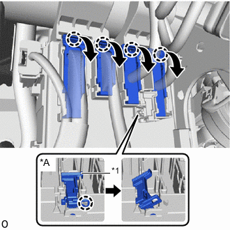
*A w/ Connector Stopper *1 Connector Stopper w/o Connector Stopper:
-
Release the connector lock lever and disconnect the connector.
Tech Tips
Use the same procedure to disconnect the remaining 3 connectors.
-
-
w/ Connector Stopper:
-
Detach the claw and release the connector stopper.
-
Release the connector lock lever and disconnect the connector.
Tech Tips
Use the same procedure to disconnect the remaining 3 connectors.
-
-
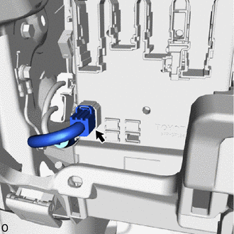
Disconnect the connector from the lower side of the instrument panel junction block assembly.
-
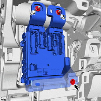
Remove the bolt, 2 nuts and instrument panel junction block assembly.
-
Disconnect the 3 connectors from the multiplex network body ECU (main body ECU).
-
-
REMOVE MULTIPLEX NETWORK BODY ECU (MAIN BODY ECU)
Note
-
If the multiplex network body ECU (main body ECU) is replaced, replace it with a new one.
-
If the multiplex network body ECU (main body ECU) is replaced, refer to the Service Bulletin.
-
As the door control battery is installed between the vehicle battery and main body ECU (multiplex network body ECU), first perform the inspections in On-Vehicle Inspection to confirm that there are no malfunctions in the power source circuit for the main body ECU (multiplex network body ECU) before performing this troubleshooting procedure.*
*: w/ Rear Pretensioner
-
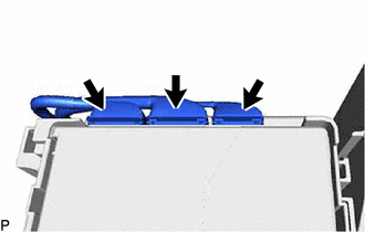
*1 Claw of Junction Block 
Protective Tape Press the claw of the junction block as shown in the illustration to release the lock.
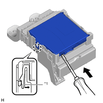
-
With the junction block lock released, insert a screwdriver with its tip wrapped with protective tape horizontally between the multiplex network body ECU (main body ECU) and junction block.
Note
Use a screwdriver with a diameter of between 5.0 mm (0.197 in.) and 6.3 mm (0.248 in.) and a length of approximately 90 mm (3.54 in.).
-
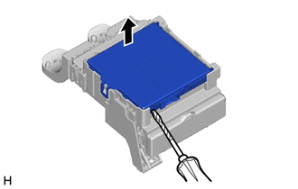
Protective Tape Using the screwdriver, carefully raise the multiplex network body ECU (main body ECU) up to the position where the connector becomes disengaged.
Note
-
Do not insert the screwdriver opening between the junction block and the connector of the multiplex network body ECU (main body ECU).
-
Do not twist the screwdriver to raise the multiplex network body ECU (main body ECU).
-
-
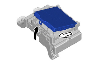

Raise 
Slide Out Raise the multiplex network body ECU (main body ECU) as shown by the black arrow, and then slide it out as shown by the white arrow in the illustration.
Note
Do not touch the ECU connector.
-