CHARGING SYSTEM, Diagnostic DTC:P162B
| DTC Code | DTC Name |
|---|---|
| P162B | Lost Communication with Battery Monitor Module |
DESCRIPTION
The ECM and battery state sensor assembly each detect reception malfunctions. A battery state sensor assembly reception malfunction detected by the battery state sensor assembly is sent to the ECM via LIN communication. If there is a malfunction in either the ECM or battery state sensor assembly, the ECM determines that there is a LIN communication malfunction and outputs a DTC.
| DTC No. | Detection Item | DTC Detection Condition | Trouble Area | Warning Indicate | Memory |
|---|---|---|---|---|---|
| P162B | Lost Communication with Battery Monitor Module | Diagnosis condition: Engine switch on (IG) When the ECM cannot receive LIN communication, the battery state sensor assembly cannot receive LIN communication for approximately 33 seconds or more. Other: 1 trip |
|
Not displayed | DTC stored |
CAUTION / NOTICE / HINT
Note
Inspect the fuses for circuits related to this system before performing the following inspection procedure.
PROCEDURE
-
CHECK BATTERY STATE SENSOR ASSEMBLY INSTALLATION CONDITION
-
Check the installation condition of the battery state sensor assembly.
Result Proceed to OK NG
NG 
INSTALL BATTERY STATE SENSOR ASSEMBLY CORRECTLY Click here
OK 
-
-
CHECK CHARGING SYSTEM
-
Check the charging system.
Result Result OK NG
NG
REPAIR OR REPLACE CHARGING SYSTEM
OK
-
-
CHECK HARNESS AND CONNECTOR (ECM - BATTERY STATE SENSOR ASSEMBLY)
-
Disconnect the C65 ECM connector.
-
Disconnect the C55 battery state sensor assembly connector.
-
Disconnect the C18 generator assembly connector.
-
Measure the resistance according to the value(s) in the table below.
Standard Resistance Tester Connection Condition Specified Condition C65-61 (LIN) - C55-2 (LIN1) Always Below 1 Ω C65-61 (LIN) or C55-2 (LIN1) - Body ground Engine switch off
(while LIN communication is stopped)
10 kΩ or higher Result Proceed to OK NG
NG
REPAIR OR REPLACE HARNESS OR CONNECTOR
OK
-
-
CHECK HARNESS AND CONNECTOR (POWER SOURCE CIRCUIT)
-
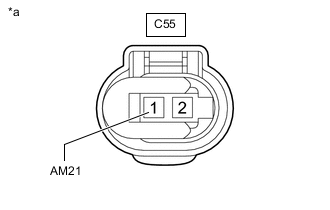
*a Front view of wire harness connector
(to Battery State Sensor Assembly)
Disconnect the C55 battery state sensor assembly connector.
-
Measure the voltage according to the value(s) in the table below.
Standard Voltage Tester Connection Condition Specified Condition C55-1 (AM21) - Body ground Engine switch on (IG) 11 to 14 V Result Result OK NG
NG
REPAIR OR REPLACE HARNESS OR CONNECTOR
OK
-
-
READ OUTPUT DTC
-
Connect the GTS to the DLC3.
-
Turn the engine switch on (IG).
-
Turn the GTS on.
-
Clear the DTCs.
Powertrain > Engine and ECT > Clear DTCs -
Turn the engine switch off and wait at least 30 seconds.
-
Start the engine and wait 17 minutes or more.
-
Enter the following menus: Powertrain / Engine and ECT / Trouble Codes.
-
Read the DTCs.
Powertrain > Engine and ECT > Trouble CodesResult Result Proceed to DTC P162B is output A P161A and P162B are output B No DTC is output C
A
REPLACE BATTERY STATE SENSOR ASSEMBLY Click here
B
REPLACE ECM Click here
C
CHECK FOR INTERMITTENT PROBLEMS Click here
-