LIN COMMUNICATION SYSTEM Air Conditioning Control Panel does not Operate
DESCRIPTION
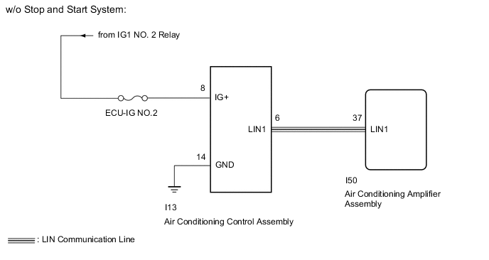
A malfunction occurs in LIN communication of the components related to the air conditioning between the air conditioning amplifier and air conditioning control.
WIRING DIAGRAM
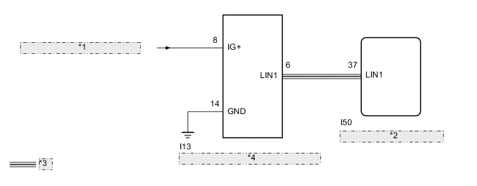
| *1 | from Engine Stop and Stert ECU |
| *2 | Air Conditioning Amplifier Assembly |
| *3 | LIN Communication Line |
| *4 | Air Conditioning Control Assembly |
CAUTION / NOTICE / HINT
Note
Inspect the fuses for circuits related to this system before performing the following inspection procedure.
PROCEDURE
-
CHECK HARNESS AND CONNECTOR (AIR CONDITIONING CONTROL ASSEMBLY - BATTERY AND BODY GROUND)
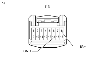
*a Front view wire harness connector
(to Air Conditioning Control Assembly)
-
Disconnect the air conditioning control assembly connector.
-
Measure the resistance according to the value(s) in the table below.
Standard Resistance w/o Stop and Start System Tester Connection Condition Specified Condition I13-14 (GND) - Body ground Always Below 1 Ω w/ Stop and Start System Tester Connection Condition Specified Condition I13-14 (GND) - Body ground Always Below 1 Ω -
Measure the voltage according to the value(s) in the table below.
Standard Voltage w/o Stop and Start System Tester Connection Switch Condition Specified Condition I13-8 (IG+) - Body ground Engine switch on (IG) 11 to 14 V w/ Stop and Start System Tester Connection Switch Condition Specified Condition I13-8 (IG+) - Body ground Engine switch on (IG) 10.5 to 16 V Result Proceed to OK NG
NG 
REPAIR OR REPLACE HARNESS OR CONNECTOR
OK 
-
-
CHECK HARNESS AND CONNECTOR (AIR CONDITIONING AMPLIFIER ASSEMBLY - AIR CONDITIONING CONTROL ASSEMBLY)
-
Disconnect the I50 air conditioning control assembly connector.
-
Disconnect the I13 air conditioning amplifier assembly connector.
-
Measure the resistance according to the value(s) in the table below.
Standard Resistance Tester Connection Condition Specified Condition I50-37 (LIN1) - I13-6 (LIN1) Always Below 1 Ω I50-37 (LIN1) or I13-6 (LIN1) - Body ground Always 10 kΩ or higher Result Proceed to OK NG
OK
GO TO AIR CONDITIONING SYSTEM Click here
NG
REPAIR OR REPLACE HARNESS OR CONNECTOR
-