PANORAMIC VIEW MONITOR SYSTEM ECU Power Source Circuit
DESCRIPTION
This circuit is the power source circuit to operate the parking assist ECU. The parking assist ECU controls the panoramic view monitor system.
WIRING DIAGRAM
Figure 1. w/o Stop and Start System
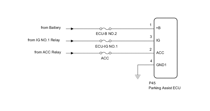
Figure 2. w/ Stop and Start System
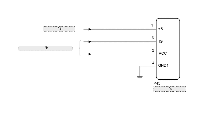
| *a | from BBC NO.3 Fuse |
| *b | from Engine Stop and Start ECU |
| *c | Parking Assist ECU |
CAUTION / NOTICE / HINT
Note
Inspect the fuse for circuits related to this system before performing the following procedure.
Tech Tips
-
If the television camera controller does not operate due to a power source problem, other system DTCs may be stored due to a CAN communication interruption.
-
w/ Stop and Start System:
The panoramic view monitor system troubleshooting procedure is based on the premise that the stop and start system is operating normally. Check the stop and start system first before troubleshooting the panoramic view monitor system.
PROCEDURE
-
CHECK HARNESS AND CONNECTOR (PARKING ASSIST ECU - BATTERY AND BODY GROUND)
-
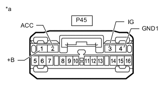
*a Front view of wire harness connector
(to Parking Assist ECU)
Disconnect the parking assist ECU connector.
-
Measure the resistance according to the value(s) in the table below.
Standard Resistance Tester Connection Condition Specified Condition P45-4 (GND1) - Body ground Always Below 1 Ω -
Measure the voltage according to the value(s) in the table below.
Standard Voltage Tester Connection Condition Specified Condition P45-1 (+B) - P45-4 (GND1) Always 11 to 14 V P45-2 (ACC) - P45-4 (GND1) Engine switch on (ACC) 11 to 14 V*1
10.5 to 16 V*2
Engine switch off Below 1 V P45-3 (IG) - P45-4 (GND1) Engine switch on (IG) 11 to 14 V*1
10.5 to 16 V*2
Engine switch off Below 1 V
-
*1: w/o Stop and Start System
-
*2: w/ Stop and Start System
Result Proceed to OK NG -
OK 
PROCEED TO NEXT SUSPECTED AREA SHOWN IN PROBLEM SYMPTOMS TABLE Click here
NG
REPAIR OR REPLACE HARNESS OR CONNECTOR
-