PANORAMIC VIEW MONITOR SYSTEM, Diagnostic DTC:C1625
| DTC Code | DTC Name |
|---|---|
| C1625 | Open or Short in Steering Angle Sensor +B |
DESCRIPTION
This DTC is stored if the parking assist ECU receives a signal via CAN communication from the spiral with sensor cable sub-assembly that indicates a power supply system problem.
| DTC No. | Detection Item | DTC Detection Condition | Trouble Area |
|---|---|---|---|
| C1625 | Open or Short in Steering Angle Sensor +B | Open or short in steering angle sensor +B |
|
WIRING DIAGRAM
Figure 1. w/o Stop and Start System
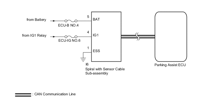
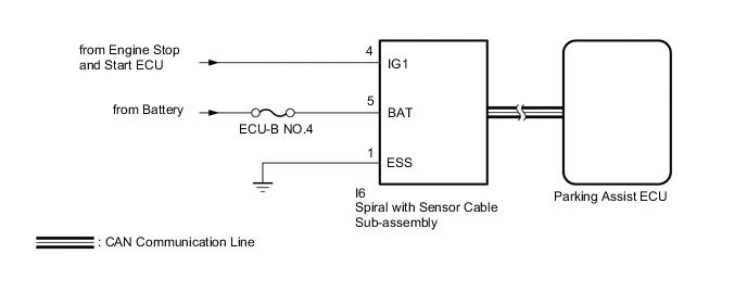
Figure 2. w/ Stop and Start System
CAUTION / NOTICE / HINT
Note
-
Since the panoramic view monitor system has functions that use the CAN communication system, first confirm that there is no malfunction in the communication system by inspecting the CAN communication functions in accordance with the "How to Proceed with Troubleshooting" procedures. Then, conduct the following inspection procedure.
-
When "System initialising" is displayed on the parking assist ECU after the cable is disconnected from the negative (-) battery terminal, correct the steering angle neutral point.
-
Depending on the parts that are replaced or operations that are performed during vehicle inspection or maintenance, calibration of other systems as well as the panoramic view monitor system may be needed.
-
Inspect the fuses for circuits related to this system before performing the following inspection procedure.
-
The vehicle is equipped with a Supplemental Restraint System (SRS) which includes components such as airbags. Before servicing (including removal or installation of parts), be sure to read the precaution for Supplemental Restraint System.
Tech Tips
w/ Stop and Start System:
The panoramic view monitor system troubleshooting procedure is based on the premise that the stop and start system normally. Check the stop and start system first before troubleshooting the panoramic view monitor system
PROCEDURE
-
CHECK HARNESS AND CONNECTOR (SPIRAL WITH SENSOR CABLE SUB-ASSEMBLY - BATTERY AND BODY GROUND)
-
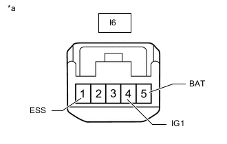
*a Front view of wire harness connector
(to Spiral with Sensor Cable Sub-assembly)
Disconnect the spiral with sensor cable sub-assembly connector.
-
Measure the resistance according to the value(s) in the table below.
Standard Resistance Tester Connection Condition Specified Condition I6-1 (ESS) - Body ground Always Below 1 Ω -
Measure the voltage according to the value(s) in the table below.
Standard Voltage *1: w/o Stop and Start SystemTester Connection Condition Specified Condition I6-4 (IG1) - I6-1 (ESS) Engine switch on (IG) 11 to 14 V*1
10.5 to 16 V*2
I6-5 (BAT) - I6-1 (ESS) Always 11 to 14 V
*2: w/ Stop and Start System
Result Proceed to OK NG
OK 
REPLACE SPIRAL WITH SENSOR CABLE SUB-ASSEMBLY Click here
NG
REPAIR OR REPLACE HARNESS OR CONNECTOR
-