BLIND SPOT MONITOR SYSTEM, Diagnostic DTC:U0232
| DTC Code | DTC Name |
|---|---|
| U0232 | Lost Communication with Blind Spot Monitor Slave Module |
DESCRIPTION
This DTC is stored when the blind spot monitor sensor LH judges that there is a communication error with the blind spot monitor sensor RH.
| DTC No. | Detection Item | DTC Detection Condition | Trouble Area | Note |
|---|---|---|---|---|
| U0232 | Lost Communication with Blind Spot Monitor Slave Module | The blind spot monitor sensor LH cannot receive signals from the blind spot monitor sensor RH. |
|
- |
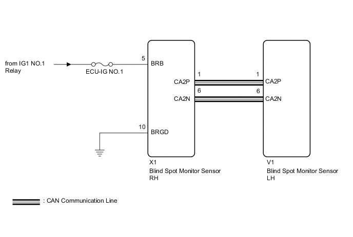
WIRING DIAGRAM
CAUTION / NOTICE / HINT
Note
-
When checking for DTCs, make sure that the blind spot monitor main switch (multi-function switch) is on.
-
Inspect the fuses for circuits related to this system before performing the following inspection procedure.
PROCEDURE
-
CHECK HARNESS AND CONNECTOR (BLIND SPOT MONITOR SENSOR RH - BLIND SPOT MONITOR SENSOR LH)
-
Disconnect the X1 blind spot monitor sensor RH connector.
-
Disconnect the V1 blind spot monitor sensor LH connector.
-
Measure the resistance according to the value(s) in the table below.
Standard Resistance Tester Connection Condition Specified Condition X1-1 (CA2P) - V1-1 (CA2P) Always Below 1 Ω X1-6 (CA2N) - V1-6 (CA2N) Always Below 1 Ω Result Proceed to OK NG
NG 
REPAIR OR REPLACE CAN LINE OR CONNECTOR
OK 
-
-
CHECK HARNESS AND CONNECTOR (BLIND SPOT MONITOR SENSOR RH - BATTERY AND BODY GROUND)
-
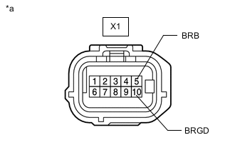
*a Front view of wire harness connector
(to Blind Spot Monitor Sensor RH)
Disconnect the blind spot monitor sensor RH connector.
-
Measure the voltage according to the value(s) in the table below.
Standard Voltage Tester Connection Switch Condition Specified Condition X1-5 (BRB) - Body ground Engine switch on (IG) 11 to 14 V -
Measure the resistance according to the value(s) in the table below.
Standard Resistance Tester Connection Condition Specified Condition X1-10 (BRGD) - Body ground Always Below 1 Ω Result Proceed to OK NG
NG
REPAIR OR REPLACE HARNESS OR CONNECTOR
OK
-
-
REPLACE BLIND SPOT MONITOR SENSOR RH
-
Replace the blind spot monitor sensor RH.
Result Proceed to NEXT
NEXT
-
-
CHECK DTC
-
Clear the DTCs.
Body Electrical > Blind Spot Monitor Master > Clear DTCs -
Recheck for DTCs and check if the same DTC is output again.
Body Electrical > Blind Spot Monitor Master > Trouble CodesOK DTC U0232 is not output. Result Proceed to OK NG
OK
END (BLIND SPOT MONITOR SENSOR RH WAS DEFECTIVE)
NG
REPLACE BLIND SPOT MONITOR SENSOR LH Click here
-