PARKING ASSIST MONITOR SYSTEM Guide Lines are Displayed with Vehicle Center Line
DESCRIPTION
The rear television camera assembly can create parking guide lines. Since this function is not necessary on vehicles with the parking assist monitor system, the guide line creation function of the rear television camera assembly is disabled.
WIRING DIAGRAM
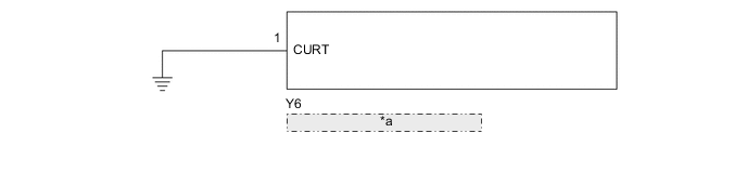
| *a | Rear Television Camera Assembly |
CAUTION / NOTICE / HINT
Note
-
When "System initializing" is displayed on the radio receiver assembly after disconnecting the cable from the negative (-) battery terminal, correct the steering angle neutral point.
-
Depending on the parts that are replaced or operations that are performed during vehicle inspection or maintenance, calibration of other systems as well as the parking assist monitor system may be needed.
PROCEDURE
-
CHECK SCREEN MODE
-
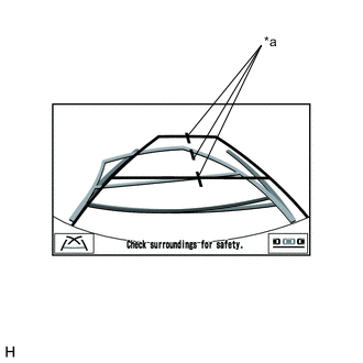
*a Vehicle Center Line Check the back guide monitor screen.
Result Result Proceed to Guide lines are displayed without vehicle center line. A Guide lines are displayed with vehicle center line. B
A 
USE SIMULATION METHOD TO CHECK (A WIRE MAY BE OPEN) Click here
B 
-
-
CHECK HARNESS AND CONNECTOR (REAR TELEVISION CAMERA ASSEMBLY - BODY GROUND)
-
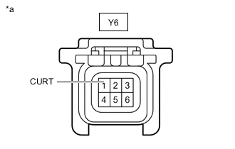
*a Front view of wire harness connector
(to Rear Television Camera Assembly)
Disconnect the rear television camera assembly connector.
-
Measure the resistance according to the value(s) in the table below.
Standard Resistance Tester Connection Condition Specified Condition Y6-1 (CURT) - Body ground Always Below 1 Ω Result Proceed to OK NG
OK
REPLACE REAR TELEVISION CAMERA ASSEMBLY Click here
NG
REPAIR OR REPLACE HARNESS OR CONNECTOR
-