MULTI-DISPLAY REMOVAL
PROCEDURE
-
PRECAUTION
Note
After turning the engine switch off, waiting time may be required before disconnecting the cable from the battery terminal. Therefore, make sure to read the disconnecting the cable from the battery terminal notice before proceeding with work.
-
DISCONNECT CABLE FROM NEGATIVE BATTERY TERMINAL
Note
When disconnecting the cable, some systems need to be initialized after the cable is reconnected.
-
REMOVE DOOR SCUFF PLATE ASSEMBLY RH (for RHD)
-
REMOVE COWL SIDE TRIM BOARD RH (for RHD)
-
REMOVE CONSOLE ARMREST ASSEMBLY
-
REMOVE UPPER REAR CONSOLE PANEL
-
REMOVE UPPER NO. 1 CONSOLE PANEL GARNISH
-
REMOVE UPPER NO. 2 CONSOLE PANEL GARNISH
-
REMOVE INSTRUMENT SIDE PANEL RH
-
REMOVE INSTRUMENT SIDE PANEL LH
-
REMOVE NO. 1 INSTRUMENT PANEL SAFETY PAD SUB-ASSEMBLY
-
REMOVE NO. 1 INSTRUMENT PANEL UNDER COVER SUB-ASSEMBLY
-
REMOVE LOWER NO. 1 INSTRUMENT PANEL FINISH PANEL
-
REMOVE NO. 1 SWITCH HOLE BASE
-
REMOVE NO. 2 INSTRUMENT PANEL SAFETY PAD SUB-ASSEMBLY
-
REMOVE CENTER INSTRUMENT CLUSTER FINISH PANEL ASSEMBLY
-
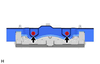
REMOVE MULTI-DISPLAY ASSEMBLY WITH BRACKET
-
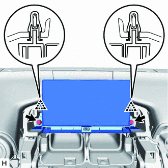
Remove the 2 bolts and detach the 2 clips.
-
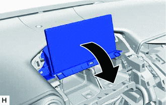
Move the multi-display assembly with bracket in the direction indicated by the arrow shown in the illustration.
-
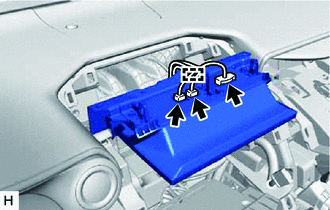
Disconnect each connector.
-
Detach the clamp and remove the multi-display assembly with bracket.
-
-
REMOVE MULTI-DISPLAY CONTROLLER BRACKET A
-
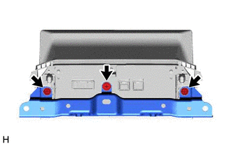
Remove the 3 screws.
-
Remove the 2 screws and multi-display controller bracket A.
-
-
REMOVE MULTI-DISPLAY ASSEMBLY