NAVIGATION SYSTEM Microphone Circuit
DESCRIPTION
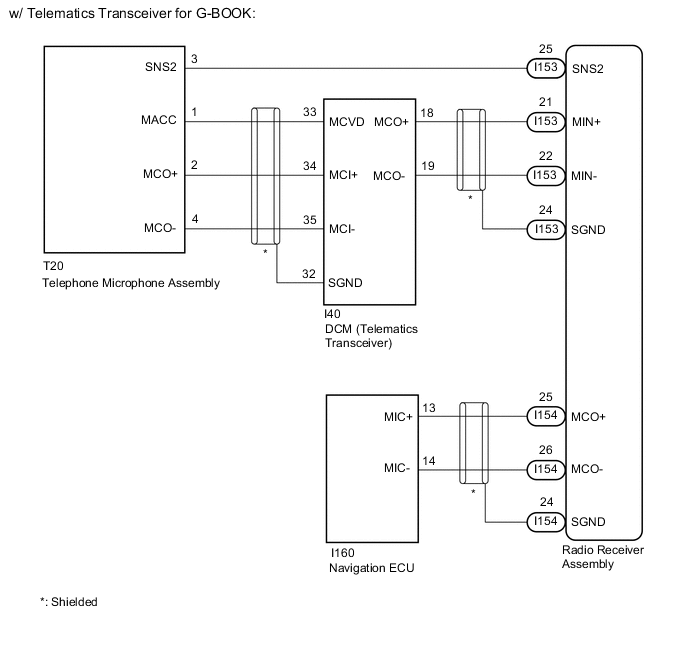
w/ Telematics Transceiver for G-BOOK:
-
The radio receiver assembly and telephone microphone assembly are connected to each other using the microphone connection detection signal lines.
-
Using this circuit, the DCM (telematics transceiver) sends power to the telephone microphone assembly, and the telephone microphone assembly sends microphone signals to the radio receiver assembly and navigation ECU.
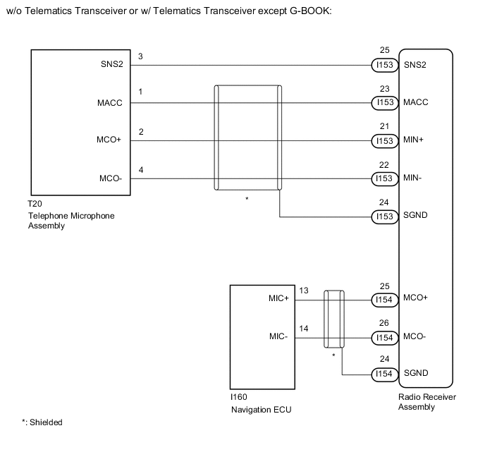
w/o Telematics Transceiver or w/ Telematics Transceiver except G-BOOK:
-
The radio receiver assembly and telephone microphone assembly are connected to each other using the microphone connection detection signal lines.
-
Using this circuit, the radio receiver assembly sends power to the telephone microphone assembly, and the telephone microphone assembly sends microphone signals to the radio receiver assembly and navigation ECU.
WIRING DIAGRAM
CAUTION / NOTICE / HINT
Note
When replacing the radio receiver assembly, always replace it with a new one.
If a radio receiver assembly which was installed to another vehicle is used, the following may occur:
-
A communication malfunction DTC may be stored.
-
The radio receiver assembly may not operate normally.
Tech Tips
Depending on the parts that are replaced during vehicle inspection or maintenance, performing initialization, registration or calibration may be needed. Refer to Precaution for Navigation System.
PROCEDURE
-
CHECK VEHICLE TYPE
-
Check the vehicle type. Refer to Check Microphone (Input to navigation ECU) in Operation Check.
Result Result Proceed to w/o Recording Function A w/ Recording Function B
B 
CHECK MICROPHONE AND VOICE RECOGNITION (INPUT TO NAVIGATION ECU) Click here
A 
-
-
CHECK MICROPHONE AND VOICE RECOGNITION (INPUT TO NAVIGATION ECU)
-
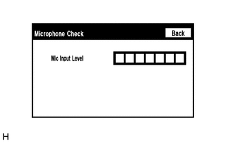
Enter the "Microphone Check" screen. Refer to Check Microphone (Input to navigation ECU) in Operation Check.
-
When voice is input into the microphone, check that the microphone input level meter changes according to the input voice.
Tech Tips
The microphone is active at all times when "Microphone Check" screen is displayed.
OK Microphone input level meter changes according to the input voice. Result Proceed to OK NG
OK 
PROCEED TO NEXT SUSPECTED AREA SHOWN IN PROBLEM SYMPTOMS TABLE Click here
NG
-
-
CHECK MICROPHONE AND VOICE RECOGNITION (INPUT TO RADIO RECEIVER ASSEMBLY)
-
Enter the "Microphone Check" screen. Refer to Check Microphone (Input to radio receiver assembly) in Operation Check.
-
When voice is input into the microphone, check that the microphone input level meter changes according to the input voice.
Tech Tips
The microphone is active at all times when "Microphone Check" screen is displayed.
OK Microphone input level meter changes according to the input voice. Result Proceed to OK NG
OK
REPAIR OR REPLACE HARNESS OR CONNECTOR (RADIO RECEIVER ASSEMBLY - NAVIGATION ECU)
NG
GO TO STEP 6 Click here
-
-
CHECK MICROPHONE AND VOICE RECOGNITION (INPUT TO NAVIGATION ECU)
-
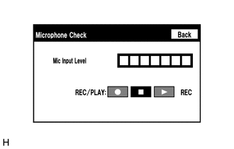
Enter the "Microphone Check" screen. Refer to Check Microphone (Input to navigation ECU) in Operation Check.
-
When voice is input into the microphone, check that the microphone input level meter changes according to the input voice.
Tech Tips
The microphone is active at all times when "Microphone Check" screen is displayed.
-
Push the recording switch and perform voice recording.
Tech Tips
-
Select the recording switch with the blower motor of the air conditioning system stopped. If an outlet of the air conditioning system is facing the microphone, noise may be recorded.
-
Voice can be recorded for up to 5 seconds.
-
-
Check that the recording indicator remains on while recording and that the recorded voice is played normally without noise or distortion.
OK All check results are normal. Result Proceed to OK NG
OK
PROCEED TO NEXT SUSPECTED AREA SHOWN IN PROBLEM SYMPTOMS TABLE Click here
NG
-
-
CHECK MICROPHONE AND VOICE RECOGNITION (INPUT TO RADIO RECEIVER ASSEMBLY)
-
Enter the "Microphone Check" screen. Refer to Check Microphone (Input to radio receiver assembly) in Operation Check.
-
When voice is input into the microphone, check that the microphone input level meter changes according to the input voice.
Tech Tips
The microphone is active at all times when "Microphone Check" screen is displayed.
-
Push the recording switch and perform voice recording.
Tech Tips
-
Select the recording switch with the blower motor of the air conditioning system stopped. If an outlet of the air conditioning system is facing the microphone, noise may be recorded.
-
Voice can be recorded for up to 5 seconds.
-
-
Check that the recording indicator remains on while recording and that the recorded voice is played normally without noise or distortion.
OK All check results are normal. Result Proceed to OK NG
OK
REPAIR OR REPLACE HARNESS OR CONNECTOR (RADIO RECEIVER ASSEMBLY - NAVIGATION ECU)
NG
-
-
CHECK VEHICLE TYPE
-
Check the vehicle type.
Result Result Proceed to w/ Telematics Transceiver for G-BOOK A w/o Telematics Transceiver or w/Telematics Transceiver except GBOOK B
B
CHECK HARNESS AND CONNECTOR (RADIO RECEIVER ASSEMBLY - TELEPHONE MICROPHONE ASSEMBLY) Click here
A
-
-
CHECK HARNESS AND CONNECTOR (RADIO RECEIVER ASSEMBLY - TELEPHONE MICROPHONE ASSEMBLY)
-
Disconnect the I153 radio receiver assembly connector.
-
Disconnect the T20 telephone microphone assembly connector.
-
Measure the resistance according to the value(s) in the table below.
Standard Resistance Tester Connection Condition Specified Condition I153-25 (SNS2) - T20-3 (SNS2) Always Below 1 Ω I153-25 (SNS2) - Body ground Always 10 kΩ or higher Result Proceed to OK NG
NG
REPAIR OR REPLACE HARNESS OR CONNECTOR
OK
-
-
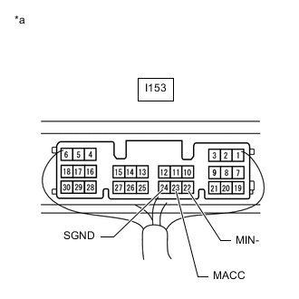
CHECK HARNESS AND CONNECTOR (RADIO RECEIVER ASSEMBLY - DCM [TELEMATICS TRANSCEIVER])
-
Disconnect the I153 radio receiver assembly connector.
-
Disconnect the I40 DCM (telematics transceiver) connector.
-
Measure the resistance according to the value(s) in the table below.
Standard Resistance Tester Connection Condition Specified Condition I153-21 (MIN+) - I40-18 (MCO+) Always Below 1 Ω I153-22 (MIN-) - I40-19 (MCO-) Always Below 1 Ω I153-21 (MIN+) - Body ground Always 10 kΩ or higher I153-22 (MIN-) - Body ground Always 10 kΩ or higher I153-24 (SGND) - Body ground Always 10 kΩ or higher Result Proceed to OK NG
NG
REPAIR OR REPLACE HARNESS OR CONNECTOR
OK
-
-
CHECK HARNESS AND CONNECTOR (DCM [TELEMATICS TRANSCEIVER] - TELEPHONE MICROPHONE ASSEMBLY)
-
Disconnect the I40 DCM (telematics transceiver) connector.
-
Disconnect the T20 telephone microphone assembly connector.
-
Measure the resistance according to the value(s) in the table below.
Standard Resistance Tester Connection Condition Specified Condition I40-33 (MCVD) - T20-1 (MACC) Always Below 1 Ω I40-34 (MCI+) - T20-2 (MCO+) Always Below 1 Ω I40-35 (MCI-) - T20-4 (MCO-) Always Below 1 Ω I40-33 (MCVD) - Body ground Always 10 kΩ or higher I40-34 (MCI+) - Body ground Always 10 kΩ or higher I40-35 (MCI-) - Body ground Always 10 kΩ or higher I40-32 (SGND) - Body ground Always 10 kΩ or higher Result Proceed to OK NG
NG
REPAIR OR REPLACE HARNESS OR CONNECTOR
OK
-
-
CHECK DCM (TELEMATICS TRANSCEIVER)
-
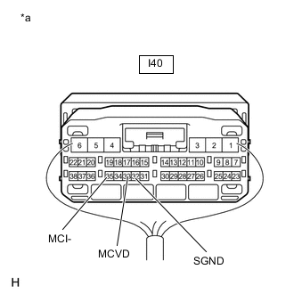
*a Component with harness connected
(DCM [Telematics Transceiver])
Remove the DCM (telematics transceiver) with the connector(s) still connected.
-
Measure the voltage according to the value(s) in the table below.
Standard Voltage Tester Connection Switch Condition Specified Condition I40-33 (MCVD) - Body ground Engine switch on (ACC) 4 to 6 V -
Measure the resistance according to the value(s) in the table below.
Standard Resistance Tester Connection Condition Specified Condition I40-32 (SGND) - Body ground Always Below 1 Ω I40-35 (MCI-) - Body ground Always Below 1 Ω Result Proceed to OK NG
NG
REPLACE DCM (TELEMATICS TRANSCEIVER) Click here
OK
-
-
CHECK TELEPHONE MICROPHONE ASSEMBLY (OUTPUT TO DCM [TELEMATICS TRANSCEIVER])
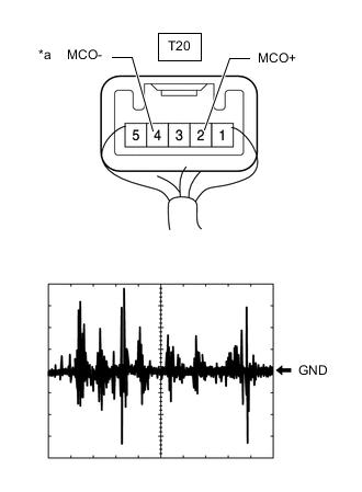
*a Component with harness connected
(Telephone Microphone Assembly)
-
Check the output waveform.
-
Remove the telephone microphone assembly with the connector(s) still connected.
-
Connect an oscilloscope to terminal T20-2 (MCO+) and T20-4 (MCO-).
-
Turn the engine switch on (ACC).
-
Sound is input to the telephone microphone assembly when the user is closer than 125 mm from the telephone microphone assembly sound holes in the No.1 microphone case.
-
Check the signal waveform according to the condition(s) in the table below.
Item Condition Measurement terminal T20-2 (MCO+) - T20-4 (MCO-) Tool setting 50 mV/DIV., 500 ms/DIV. Vehicle condition
-
Engine switch on (ACC)
-
Sound is input to the telephone microphone assembly when the user is closer than 125 mm from the telephone microphone assembly sound holes in the No.1 microphone case.
OK The waveform is similar to that shown in the illustration. Tech Tips
The oscilloscope waveform shown in the illustration is an example for reference only.
-
Result Proceed to OK NG -
NG
REPLACE TELEPHONE MICROPHONE ASSEMBLY Click here
OK
-
-
CHECK DCM (TELEMATICS TRANSCEIVER) (OUTPUT TO RADIO RECEIVER ASSEMBLY)
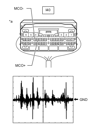
*a Component with harness connected
(DCM [Telematics Transceiver])
-
Check the output waveform.
-
Remove the DCM (telematics transceiver) with the connector(s) still connected.
-
Connect an oscilloscope to terminal I40-18 (MCO+) and I40-19 (MCO-).
-
Turn the engine switch on (ACC).
-
Sound is input to the telephone microphone assembly when the user is closer than 125 mm from the telephone microphone assembly sound holes in the No.1 microphone case.
-
Check the signal waveform according to the condition(s) in the table below.
Item Condition Measurement terminal I40-18 (MCO+) - I40-19 (MCO-) Tool setting 50 mV/DIV., 500 ms/DIV. Vehicle condition
-
Engine switch on (ACC)
-
Sound is input to the telephone microphone assembly when the user is closer than 125 mm from the telephone microphone assembly sound holes in the No.1 microphone case.
OK The waveform is similar to that shown in the illustration. Tech Tips
The oscilloscope waveform shown in the illustration is an example for reference only.
-
Result Proceed to OK NG -
OK
REPLACE RADIO RECEIVER ASSEMBLY Click here
NG
REPLACE DCM (TELEMATICS TRANSCEIVER) Click here
-
-
CHECK HARNESS AND CONNECTOR (RADIO RECEIVER ASSEMBLY - TELEPHONE MICROPHONE ASSEMBLY)
-
Disconnect the I153 radio receiver assembly connector.
-
Disconnect the T20 telephone microphone assembly connector.
-
Measure the resistance according to the value(s) in the table below.
Standard Resistance Tester Connection Condition Specified Condition I153-25 (SNS2) - T20-3 (SNS2) Always Below 1 Ω I153-23 (MACC) - T20-1 (MACC) Always Below 1 Ω I153-21 (MIN+) - T20-2 (MCO+) Always Below 1 Ω I153-22 (MIN-) - T20-4 (MCO-) Always Below 1 Ω I153-25 (SNS2) - Body ground Always 10 kΩ or higher I153-23 (MACC) - Body ground Always 10 kΩ or higher I153-21 (MIN+) - Body ground Always 10 kΩ or higher I153-22 (MIN-) - Body ground Always 10 kΩ or higher I153-24 (SGND) - Body ground Always 10 kΩ or higher Result Proceed to OK NG
NG
REPAIR OR REPLACE HARNESS OR CONNECTOR
OK
-
-
CHECK RADIO RECEIVER ASSEMBLY
-
*a Component with harness connected
(Radio Receiver Assembly)
Remove the radio receiver assembly with the connector(s) still connected.
-
Measure the voltage according to the value(s) in the table below.
Standard Voltage Tester Connection Switch Condition Specified Condition I153-23 (MACC) - Body ground Engine switch on (ACC) 4 to 6 V -
Measure the resistance according to the value(s) in the table below.
Standard Resistance Tester Connection Condition Specified Condition I153-22 (MIN-) - Body ground Always Below 1 Ω I153-24 (SGND) - Body ground Always Below 1 Ω Result Proceed to OK NG
NG
REPLACE RADIO RECEIVER ASSEMBLY Click here
OK
-
-
CHECK TELEPHONE MICROPHONE ASSEMBLY (OUTPUT TO RADIO RECEIVER ASSEMBLY)

*a Component with harness connected
(Telephone Microphone Assembly)
-
Check the output waveform.
-
Remove the telephone microphone assembly with the connector(s) still connected.
-
Connect an oscilloscope to terminal T20-2 (MCO+) and T20-4 (MCO-).
-
Turn the engine switch on (ACC).
-
Sound is input to the telephone microphone assembly when the user is closer than 125 mm from the telephone microphone assembly sound holes in the roof headlining holder cover.
-
Check the signal waveform according to the condition(s) in the table below.
Item Condition Measurement terminal T20-2 (MCO+) - T20-4 (MCO-) Tool setting 50 mV/DIV., 500 ms/DIV. Vehicle condition
-
Engine switch on (ACC)
-
Sound is input to the telephone microphone assembly when the user is closer than 125 mm from the telephone microphone assembly sound holes in the roof headlining holder cover.
OK The waveform is similar to that shown in the illustration. Tech Tips
The oscilloscope waveform shown in the illustration is an example for reference only.
-
Result Proceed to OK NG -
OK
REPLACE RADIO RECEIVER ASSEMBLY Click here
NG
REPLACE TELEPHONE MICROPHONE ASSEMBLY Click here
-