NAVIGATION SYSTEM, Diagnostic DTC:B15DB
| DTC Code | DTC Name |
|---|---|
| B15DB | Telematics Transceiver Disconnected |
DESCRIPTION
If the radio receiver assembly cannot detect the DCM (telematics transceiver) for a certain period of time (90 seconds) after the engine switch is turned on (ACC) and the radio receiver assembly confirms that the information is missing by checking past DCM (telematics transceiver) recognition information (registered information), this DTC will be stored.
Tech Tips
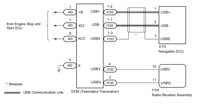
The telematics system (w/ telematics transceiver for G-BOOK) uses USB communication between devices. If an open, short, short to +B or short to ground occurs in the USB circuit, communication is interrupted and the telematics system (w/ telematics transceiver for G-BOOK) will not operate normally.
| DTC No. | Detection Item | DTC Detection Condition | Trouble Area |
|---|---|---|---|
| B15DB | Telematics Transceiver Disconnected | DCM (telematics transceiver) disconnected |
|
Tech Tips
This DTC may be stored due to environmental reasons such as electrical noise or interference.
WIRING DIAGRAM
CAUTION / NOTICE / HINT
Note
-
Inspect the fuses for circuits related to this system before performing the following procedure.
-
When replacing the DCM (telematics transceiver), make sure to replace it with a new one.
-
When replacing the radio receiver assembly or navigation ECU, always replace it with a new one.
If a radio receiver assembly or navigation ECU which was installed to another vehicle is used, the following may occur:
-
A communication malfunction DTC may be stored.
-
The radio receiver assembly or navigation ECU may not operate normally.
Tech Tips
Depending on the parts that are replaced during vehicle inspection or maintenance, performing initialization, registration or calibration may be needed. Refer to Precaution for Navigation System.
PROCEDURE
-
CHECK DTC
-
Clear the DTCs.
Body Electrical > Navigation System > Clear DTCs -
Turn the engine switch off.
-
Turn the engine switch on (IG) and wait for 90 seconds.
-
Recheck for DTCs and check that no DTCs are output.
Body Electrical > Navigation System > Trouble CodesOK No DTCs are output. Result Proceed to OK NG
OK 
USE SIMULATION METHOD TO CHECK Click here
NG 
-
-
CHECK HARNESS AND CONNECTOR (DCM [TELEMATICS TRANSCEIVER] - BATTERY AND BODY GROUND)
-
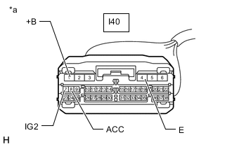
*a Front view of wire harness connector
(to DCM [Telematics Transceiver])
Disconnect the DCM (telematics transceiver) connector.
-
Measure the resistance according to the value(s) in the table below.
Standard Resistance Tester Connection Condition Specified Condition I40-4 (E) - Body ground Always Below 1 Ω -
Measure the voltage according to the value(s) in the table below.
Standard Voltage Tester Connection Condition Specified Condition I40-1 (+B) - Body ground Always 10.5 to 16 V I40-8 (ACC) - Body ground Engine switch on (ACC) 10.5 to 16 V I40-7 (IG2) - Body ground Engine switch on (IG) 10.5 to 16 V Result Proceed to OK NG
NG
REPAIR OR REPLACE HARNESS OR CONNECTOR
OK
-
-
CHECK HARNESS AND CONNECTOR (RADIO RECEIVER ASSEMBLY - DCM [TELEMATICS TRANSCEIVER])
-
Disconnect the I154 radio receiver assembly connector.
-
Disconnect the I100 DCM (telematics transceiver) connector.
-
Measure the resistance according to the value(s) in the table below.
Standard Resistance Tester Connection Condition Specified Condition I154-10 (USBV) - I100-4 (USBV) Always Below 1 Ω I154-11 (USBG) - I100-2 (USBG) Always Below 1 Ω I154-10 (USBV) - Body ground Always 10 kΩ or higher I154-11 (USBG) - Body ground Always 10 kΩ or higher Result Proceed to OK NG
NG
REPAIR OR REPLACE HARNESS OR CONNECTOR
OK
-
-
CHECK RADIO RECEIVER ASSEMBLY (USBV, USBG)
-
Disconnect the DCM (telematics transceiver) connector.
-
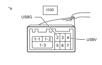
*a Front view of wire harness connector
(to DCM [Telematics Transceiver])
Measure the resistance according to the value(s) in the table below.
Standard Resistance Tester Connection Condition Specified Condition I100-2 (USBG) - Body ground Always Below 1 Ω -
Measure the voltage according to the value(s) in the table below.
Standard Voltage Tester Connection Switch Condition Specified Condition I100-4 (USBV) - I100-2 (USBG) Engine switch on (ACC) 4.75 to 5.25 V Result Proceed to OK NG
NG
REPLACE RADIO RECEIVER ASSEMBLY Click here
OK
-
-
CHECK HARNESS AND CONNECTOR (DCM [TELEMATICS TRANSCEIVER] - NAVIGATION ECU)
-
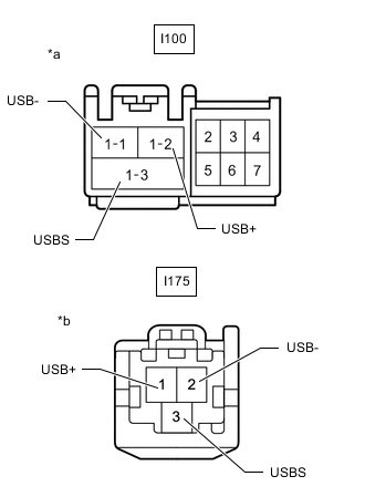
*a Front view of wire harness connector
(to DCM [Telematics Transceiver])
*b Front view of wire harness connector
(to Navigation ECU)
Disconnect the I100 DCM (telematics transceiver) connector.
-
Disconnect the I175 navigation ECU connector.
-
Measure the resistance according to the value(s) in the table below.
Standard Resistance Tester Connection Condition Specified Condition I100-1-1 (USB-) - I175-2 (USB-) Always Below 1 Ω I100-1-2 (USB+) - I175-1 (USB+) Always Below 1 Ω I100-1-3 (USBS) - I175-3 (USBS) Always Below 1 Ω I100-1-1 (USB-) - Body ground Always 10 kΩ or higher I100-1-2 (USB+) - Body ground Always 10 kΩ or higher I100-1-3 (USBS) - Body ground Always 10 kΩ or higher Result Proceed to OK NG
NG
REPAIR OR REPLACE HARNESS OR CONNECTOR
OK
-
-
CHECK DCM (TELEMATICS TRANSCEIVER)
-
Replace the DCM (telematics transceiver) with a new one.
-
Clear the DTCs.
Body Electrical > Navigation System > Clear DTCs -
Turn the engine switch off.
-
Turn the engine switch on (IG) and wait for 90 seconds.
-
Recheck for DTCs and check that no DTCs are output.
Body Electrical > Navigation System > Trouble CodesOK No DTCs are output. Result Proceed to OK NG
OK
END (DCM [TELEMATICS TRANSCEIVER] IS DEFECTIVE)
NG
-
-
CHECK NAVIGATION ECU
-
Replace the navigation ECU with a new one.
-
Clear the DTCs.
Body Electrical > Navigation System > Clear DTCs -
Turn the engine switch off.
-
Turn the engine switch on (IG) and wait for 90 seconds.
-
Recheck for DTCs and check that no DTCs are output.
Body Electrical > Navigation System > Trouble CodesOK No DTCs are output. Result Proceed to OK NG
OK
END (NAVIGATION ECU IS DEFECTIVE)
NG
REPLACE RADIO RECEIVER ASSEMBLY Click here
-