NAVIGATION SYSTEM, Diagnostic DTC:B15C0, B15C1
| DTC Code | DTC Name |
|---|---|
| B15C0 | Short in GPS Antenna |
| B15C1 | Open in GPS Antenna |
DESCRIPTION
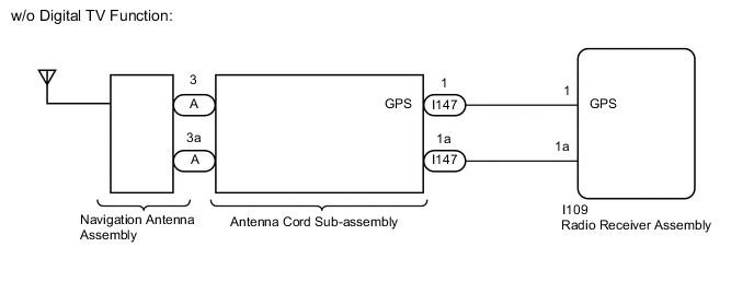
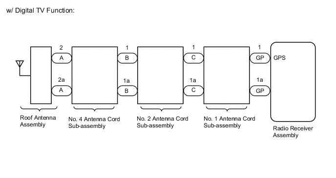
These DTCs are stored when a malfunction occurs in the navigation antenna assembly*1 or roof antenna assembly*2.
-
*1: w/o Digital TV Function
-
*2: w/ Digital TV Function
| DTC No. | Detection Item | DTC Detection Condition | Trouble Area |
|---|---|---|---|
| B15C0 | Short in GPS Antenna | Navigation antenna error |
|
| B15C1 | Open in GPS Antenna | Error of the power source to the navigation antenna |
|
WIRING DIAGRAM
CAUTION / NOTICE / HINT
Note
Depending on the parts that are replaced during vehicle inspection or maintenance, performing initialization, registration or calibration may be needed. Refer to Precaution for Navigation System.
PROCEDURE
-
CLEAR DTC
-
Clear the DTCs.
Body Electrical > Navigation System > Clear DTCsResult Proceed to NEXT
NEXT 
-
-
CHECK DTC
-
Recheck for DTCs and check if the same DTC is output again.
Body Electrical > Navigation System > Trouble CodesOK No DTCs are output. Result Proceed to OK NG
OK 
USE SIMULATION METHOD TO CHECK Click here
NG
-
-
CHECK VEHICLE TYPE
-
Check the vehicle type.
Result Result Proceed to w/o Digital TV Function A w/ Digital TV Function B
B 
INSPECT ROOF ANTENNA ASSEMBLY Click here
A
-
-
INSPECT NAVIGATION ANTENNA ASSEMBLY
-
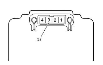
Remove the navigation antenna assembly.
-
Measure the resistance according to the value(s) in the table below.
Standard Resistance Tester Connection Condition Specified Condition 3 - 3a Always 50 to 500 Ω Result Proceed to OK NG
NG
REPLACE NAVIGATION ANTENNA ASSEMBLY Click here
OK
-
-
CHECK ANTENNA CORD SUB-ASSEMBLY
-
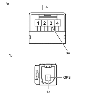
*a Front view of wire harness connector
(to Navigation Antenna Assembly)
*b Front view of wire harness connector
(to Instrument Panel Wire)
Disconnect the antenna connector from the navigation antenna assembly.
-
Disconnect the antenna connector from the instrument panel wire.
-
Measure the resistance according to the value(s) in the table below.
Standard Resistance Tester Connection Condition Specified Condition A-3 - 1 (GPS) Always Below 1 Ω A-3a - 1a Always Below 1 Ω A-3 - Body ground Always 10 kΩ or higher A-3a - Body ground Always 10 kΩ or higher Result Proceed to OK NG
NG
REPLACE ANTENNA CORD SUB-ASSEMBLY Click here
OK
-
-
CHECK HARNESS AND CONNECTOR (ANTENNA CORD SUB-ASSEMBLY - RADIO RECEIVER ASSEMBLY)
-
Disconnect the I109 radio receiver assembly connector.
-
Disconnect the I147 antenna cord sub-assembly connector.
-
Measure the resistance according to the value(s) in the table below.
Standard Resistance Tester Connection Condition Specified Condition I109-1 (GPS) - I147-1 (GPS) Always Below 1 Ω I109-1a - I147-1a Always Below 1 Ω I109-1 (GPS) - Body ground Always 10 kΩ or higher I109-1a - Body ground Always 10 kΩ or higher Result Proceed to OK NG
OK
REPLACE RADIO RECEIVER ASSEMBLY Click here
NG
REPAIR OR REPLACE HARNESS OR CONNECTOR
-
-
INSPECT ROOF ANTENNA ASSEMBLY
-
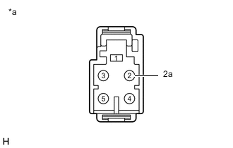
*a Roof Antenna Assembly Remove the roof antenna assembly.
-
Measure the resistance according to the value(s) in the table below.
Standard Resistance Tester Connection Condition Specified Condition 2 - 2a Always 4 to 11 kΩ Result Proceed to OK NG
NG
REPLACE ROOF ANTENNA ASSEMBLY Click here
OK
-
-
INSPECT NO. 4 ANTENNA CORD SUB-ASSEMBLY
-
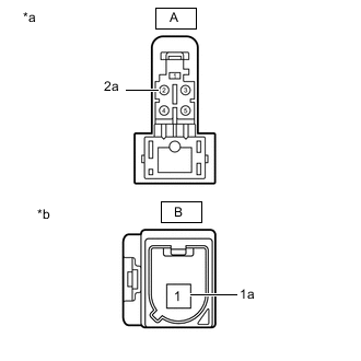
*a Front view of wire harness connector
(to Roof Antenna Assembly)
*b Front view of wire harness connector
(to No. 2 Antenna Cord Sub-assembly)
Disconnect the antenna connector from the roof antenna assembly connector.
-
Disconnect the antenna connector from the No. 2 antenna cord sub-assembly connector.
-
Measure the resistance according to the value(s) in the table below.
Standard Resistance Tester Connection Condition Specified Condition A-2 - B-1 Always Below 1 Ω A-2a - B-1a Always Below 1 Ω A-2 - Body ground Always 10 kΩ or higher A-2a - Body ground Always 10 kΩ or higher Result Proceed to OK NG
NG
REPLACE NO. 4 ANTENNA CORD SUB-ASSEMBLY Click here
OK
-
-
INSPECT NO. 2 ANTENNA CORD SUB-ASSEMBLY
-
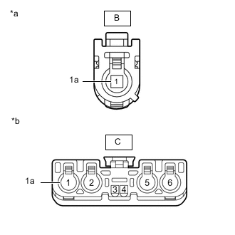
*a Front view of wire harness connector
(to No. 4 Antenna Cord Sub-assembly)
*b Front view of wire harness connector
(to No. 1 Antenna Cord Sub-assembly)
Disconnect the antenna connector from the No. 4 antenna cord sub-assembly connector.
-
Disconnect the antenna connector from the No. 1 antenna cord sub-assembly connector.
-
Measure the resistance according to the value(s) in the table below.
Standard Resistance Tester Connection Condition Specified Condition B-1 - C-1 Always Below 1 Ω B-1a - C-1a Always Below 1 Ω B-1 - Body ground Always 10 kΩ or higher B-1a - Body ground Always 10 kΩ or higher Result Proceed to OK NG
NG
REPLACE NO. 2 ANTENNA CORD SUB-ASSEMBLY Click here
OK
-
-
INSPECT NO. 1 ANTENNA CORD SUB-ASSEMBLY
-
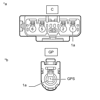
*a Front view of wire harness connector
(to No. 2 Antenna Cord Sub-assembly)
*b Front view of wire harness connector
(to Radio Receiver Assembly)
Disconnect the antenna connector from the No. 2 antenna cord sub-assembly connector.
-
Disconnect the antenna connector from the radio receiver assembly connector.
-
Measure the resistance according to the value(s) in the table below.
Standard Resistance Tester Connection Condition Specified Condition C-1 - GP-1 (GPS) Always Below 1 Ω C-1a - GP-1a Always Below 1 Ω C-1 - Body ground Always 10 kΩ or higher C-1a - Body ground Always 10 kΩ or higher Result Proceed to OK NG
OK
REPLACE RADIO RECEIVER ASSEMBLY Click here
NG
REPLACE NO. 1 ANTENNA CORD SUB-ASSEMBLY Click here
-