NAVIGATION SYSTEM, Diagnostic DTC:B1579
| DTC Code | DTC Name |
|---|---|
| B1579 | Voice Recognition Microphone Disconnected |
DESCRIPTION
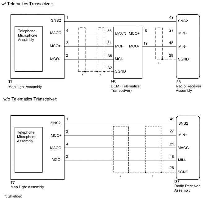
The radio receiver assembly and map light assembly (telephone microphone assembly) are connected to each other using the microphone connection detection signal lines.
This DTC is stored when a microphone connection detection signal line is disconnected.
| DTC No. | Detection Item | DTC Detection Condition | Trouble Area |
|---|---|---|---|
| B1579 | Voice Recognition Microphone Disconnected | Telephone microphone signal is lost. |
|
WIRING DIAGRAM
CAUTION / NOTICE / HINT
Tech Tips
Depending on the parts that are replaced during vehicle inspection or maintenance, performing initialization, registration or calibration may be needed. Refer to Precaution for Navigation System.
PROCEDURE
-
CONFIRM MODEL
-
Choose the model to be inspected.
Model Model Proceed to w/o Telematics Transceiver A w/ Telematics Transceiver B
B 
CHECK HARNESS AND CONNECTOR (RADIO RECEIVER ASSEMBLY - MAP LIGHT ASSEMBLY) Click here
A 
-
-
CHECK HARNESS AND CONNECTOR (RADIO RECEIVER ASSEMBLY - MAP LIGHT ASSEMBLY)
-
Disconnect the I38 radio receiver assembly connector.
-
Disconnect the T7 map light assembly connector.
-
Measure the resistance according to the value(s) in the table below.
Standard Resistance Tester Connection Condition Specified Condition I38-27 (MIN+) - T7-3 (MCO+) Always Below 1 Ω I38-29 (MACC) - T7-4 (MACC) Always Below 1 Ω I38-48 (MIN-) - T7-2 (MCO-) Always Below 1 Ω I38-49 (SNS2) - T7-1 (SNS2) Always Below 1 Ω I38-27 (MIN+) - Body ground Always 10 kΩ or higher I38-28 (SGND) - Body ground Always 10 kΩ or higher I38-29 (MACC) - Body ground Always 10 kΩ or higher I38-48 (MIN-) - Body ground Always 10 kΩ or higher I38-49 (SNS2) - Body ground Always 10 kΩ or higher Result Proceed to OK NG
NG 
REPAIR OR REPLACE HARNESS OR CONNECTOR
OK
-
-
CHECK RADIO RECEIVER ASSEMBLY
-
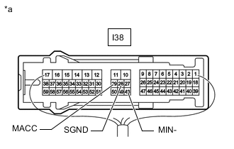
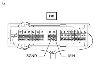
*a Component with harness connected
(Radio Receiver Assembly)
Measure the voltage according to the value(s) in the table below.
Standard Voltage Tester Connection Switch Condition Specified Condition I38-29 (MACC) - Body ground Engine switch on (ACC) 4 to 6 V -
Measure the resistance according to the value(s) in the table below.
Standard Resistance Tester Connection Condition Specified Condition I38-28 (SGND) - Body ground Always Below 1 Ω I38-48 (MIN-) - Body ground Always Below 1 Ω Result Proceed to OK NG
NG
REPLACE RADIO RECEIVER ASSEMBLY Click here
OK
-
-
INSPECT MAP LIGHT ASSEMBLY
-
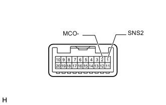
Remove the map light assembly.
-
Measure the resistance according to the value(s) in the table below.
Standard Resistance Tester Connection Condition Specified Condition 2 (MCO-) - 1 (SNS2) Always Below 1 Ω Result Proceed to OK NG
NG
GO TO STEP 6 Click here
OK
-
-
CHECK MAP LIGHT ASSEMBLY
-
Turn the engine switch on (ACC).
-
Connect an oscilloscope to terminals T7-3 (MCO+) and T7-2 (MCO-) of the map light assembly connector.
-
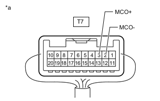
*a Component with harness connected
(Map Light Assembly)
Check the waveform of the telephone microphone assembly using the oscilloscope.
-
Proceed to the next step based on the inspection result.
Result Result Proceed to A waveform synchronized with the voice input to the map light assembly is output. A A waveform synchronized with the voice input to the map light assembly is not output. B
A
REPLACE RADIO RECEIVER ASSEMBLY Click here
B
-
-
CHECK TELEPHONE MICROPHONE ASSEMBLY
-
Replace the telephone microphone assembly.
-
Check if the same DTC is output again.
Body Electrical > Navigation System > Trouble CodesOK No DTCs are output. Result Proceed to OK NG
OK
END (TELEPHONE MICROPHONE ASSEMBLY IS DEFECTIVE)
NG
REPLACE MAP LIGHT ASSEMBLY Click here
-
-
CHECK HARNESS AND CONNECTOR (RADIO RECEIVER ASSEMBLY - MAP LIGHT ASSEMBLY)
-
Disconnect the I38 radio receiver assembly connector.
-
Disconnect the T7 map light assembly connector.
-
Measure the resistance according to the value(s) in the table below.
Standard Resistance Tester Connection Condition Specified Condition I38-49 (SNS2) - T7-1 (SNS2) Always Below 1 Ω Result Proceed to OK NG
NG
REPAIR OR REPLACE HARNESS OR CONNECTOR
OK
-
-
CHECK HARNESS AND CONNECTOR (RADIO RECEIVER ASSEMBLY - DCM [TELEMATICS TRANSCEIVER])
-
Disconnect the I38 radio receiver assembly connector.
-
Disconnect the I40 DCM (telematics transceiver) connector.
-
Measure the resistance according to the value(s) in the table below.
Standard Resistance Tester Connection Condition Specified Condition I38-27 (MIN+) - I40-18 (MCO+) Always Below 1 Ω I38-48 (MIN-) - I40-19 (MCO-) Always Below 1 Ω I38-27 (MIN+) - Body ground Always 10 kΩ or higher I38-48 (MIN-) - Body ground Always 10 kΩ or higher I38-28 (SGND) - Body ground Always 10 kΩ or higher Result Proceed to OK NG
NG
REPAIR OR REPLACE HARNESS OR CONNECTOR
OK
-
-
CHECK HARNESS AND CONNECTOR (DCM [TELEMATICS TRANSCEIVER] - MAP LIGHT ASSEMBLY)
-
Disconnect the I40 DCM (telematics transceiver) connector.
-
Disconnect the T7 map light assembly connector.
-
Measure the resistance according to the value(s) in the table below.
Standard Resistance Tester Connection Condition Specified Condition I40-33 (MCVD) - T7-4 (MACC) Always Below 1 Ω I40-34 (MCI+) - T7-3 (MCO+) Always Below 1 Ω I40-35 (MCI-) - T7-2 (MCO-) Always Below 1 Ω I40-33 (MCVD) - Body ground Always 10 kΩ or higher I40-34 (MCI+) - Body ground Always 10 kΩ or higher I40-35 (MCI-) - Body ground Always 10 kΩ or higher I40-32 (SGND) - Body ground Always 10 kΩ or higher Result Proceed to OK NG
NG
REPAIR OR REPLACE HARNESS OR CONNECTOR
OK
-
-
CHECK RADIO RECEIVER ASSEMBLY
-
*a Component with harness connected
(Radio Receiver Assembly)
Disconnect the I40 DCM (telematics transceiver) connector.
-
Measure the resistance according to the value(s) in the table below.
Standard Resistance Tester Connection Condition Specified Condition I38-28 (SGND) - Body ground Always Below 1 Ω I38-48 (MIN-) - Body ground Always Below 1 Ω Result Proceed to OK NG
NG
REPLACE RADIO RECEIVER ASSEMBLY Click here
OK
-
-
CHECK DCM (TELEMATICS TRANSCEIVER)
-
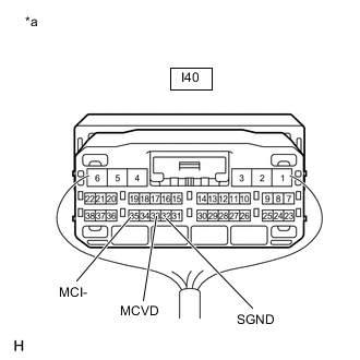
*a Component with harness connected
(DCM [Telematics Transceiver])
Measure the voltage according to the value(s) in the table below.
Standard Voltage Tester Connection Switch Condition Specified Condition I40-33 (MCVD) - Body ground Engine switch on (ACC) 4 to 6 V -
Measure the resistance according to the value(s) in the table below.
Standard Resistance Tester Connection Condition Specified Condition I40-32 (SGND) - Body ground Always Below 1 Ω I40-35 (MCI-) - Body ground Always Below 1 Ω Result Proceed to OK NG
NG
REPLACE DCM (TELEMATICS TRANSCEIVER) Click here
OK
-
-
INSPECT MAP LIGHT ASSEMBLY
-
Remove the map light assembly.
-
Measure the resistance according to the value(s) in the table below.
Standard Resistance Tester Connection Condition Specified Condition 2 (MCO-) - 1 (SNS2) Always Below 1 Ω Result Proceed to OK NG
NG
GO TO STEP 14 Click here
OK
-
-
CHECK MAP LIGHT ASSEMBLY
-
*a Component with harness connected
(Map Light Assembly)
Turn the engine switch on (ACC).
-
Connect an oscilloscope to terminals T7-3 (MCO+) and T7-2 (MCO-) of the map light assembly connector.
-
Check the waveform of the telephone microphone assembly using the oscilloscope.
Result Result Proceed to A waveform synchronized with the voice input to the map light assembly is output. A A waveform synchronized with the voice input to the map light assembly is not output. B
A
REPLACE RADIO RECEIVER ASSEMBLY Click here
B
-
-
CHECK TELEPHONE MICROPHONE ASSEMBLY
-
Replace the telephone microphone assembly.
-
Check if the same DTC is output again.
Body Electrical > Navigation System > Trouble CodesOK No DTCs are output. Result Proceed to OK NG
OK
END (TELEPHONE MICROPHONE ASSEMBLY IS DEFECTIVE)
NG
REPLACE MAP LIGHT ASSEMBLY Click here
-