RADIO RECEIVER REMOVAL
PROCEDURE
-
PRECAUTION
Note
After turning the engine switch off, waiting time may be required before disconnecting the cable from the battery terminal. Therefore, make sure to read the disconnecting the cable from the battery terminal notice before proceeding with work.
-
DISCONNECT CABLE FROM NEGATIVE BATTERY TERMINAL
CAUTION:
Wait at least 90 seconds after disconnecting the cable from the negative (-) battery terminal to disable the SRS system
Note
When disconnecting the cable, some systems need to be initialized after the cable is reconnected.
-
REMOVE INSTRUMENT PANEL FINISH PLATE
-
REMOVE MULTI-DISPLAY ASSEMBLY WITH BRACKET
-
REMOVE DOOR SCUFF PLATE ASSEMBLY RH (for RHD)
-
REMOVE COWL SIDE TRIM BOARD RH (for RHD)
-
REMOVE CONSOLE ARMREST ASSEMBLY
-
REMOVE UPPER REAR CONSOLE PANEL
-
REMOVE UPPER NO. 1 CONSOLE PANEL GARNISH
-
REMOVE UPPER NO. 2 CONSOLE PANEL GARNISH
-
REMOVE INSTRUMENT SIDE PANEL RH
-
REMOVE INSTRUMENT SIDE PANEL LH
-
REMOVE NO. 1 INSTRUMENT PANEL SAFETY PAD SUB-ASSEMBLY
-
REMOVE NO. 1 INSTRUMENT PANEL UNDER COVER SUB-ASSEMBLY
-
REMOVE LOWER NO. 1 INSTRUMENT PANEL FINISH PANEL
-
REMOVE NO. 1 SWITCH HOLE BASE
-
REMOVE NO. 2 INSTRUMENT PANEL SAFETY PAD SUB-ASSEMBLY
-
REMOVE CENTER INSTRUMENT CLUSTER FINISH PANEL ASSEMBLY
-
REMOVE SHIFT LEVER KNOB SUB-ASSEMBLY
-
REMOVE UPPER REAR CONSOLE PANEL SUB-ASSEMBLY
-
REMOVE AIR CONDITIONING CONTROL ASSEMBLY
-
REMOVE RADIO RECEIVER ASSEMBLY WITH BRACKET
-
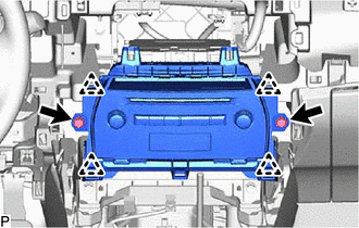
Remove the 2 bolts.
-
Pull the radio receiver assembly with bracket toward the rear of the vehicle and disengage the 4 clips.
-
Disconnect each connector and remove the radio receiver assembly with bracket.
-
-
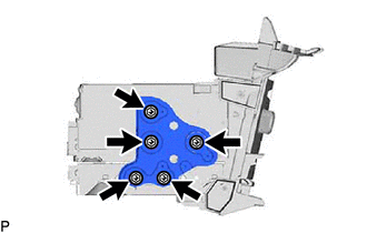
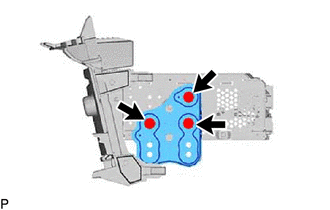
REMOVE NO. 1 RADIO BRACKET
-
w/ Navigation System
-
Remove the 3 screws and No. 1 radio bracket.
-
-
w/o Navigation System
-
Remove the 3 screws and No. 1 radio bracket.
-
-
-
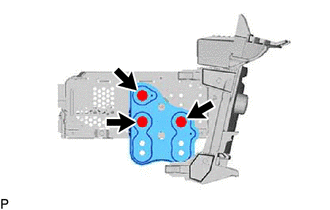
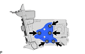
REMOVE NO. 2 RADIO BRACKET
-
w/ Navigation System
-
Remove the 3 screws and No. 2 radio bracket.
-
-
w/ Navigation System
-
Remove the 3 screws and No. 2 radio bracket.
-
-
-
REMOVE NAVIGATION ECU
-
REMOVE RADIO RECEIVER ASSEMBLY