ASC SYSTEM Main Switch Circuit
DESCRIPTION
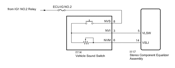
The stereo component equalizer assembly detects vehicle sound switch signals.
The ASC system can be turned on and off by operating the vehicle sound switch.
WIRING DIAGRAM
CAUTION / NOTICE / HINT
Note
Inspect the fuses for circuits related to this system before performing the following procedure.
PROCEDURE
-
READ VALUE USING GTS
-
Using the GTS, read the Data List.
Body Electrical > ASC > Data ListTester Display Measurement Item Range Normal Condition Diagnostic Note Volume SW Vehicle sound switch on/off status OFF or ON OFF: Vehicle sound switch off
ON: Vehicle sound switch on
- Volume Switch Voltage The VSLI terminal voltage to the CPU of the stereo compartment equalizer assembly Min.: 0 V
Max.: 5 V
Changes according to vehicle sound switch volume setting -
Body Electrical > ASC > Data ListTester Display Volume SW Volume Switch Voltage OK The display is as specified in the normal condition column. Result Proceed to OK NG
OK 
PROCEED TO NEXT SUSPECTED AREA SHOWN IN PROBLEM SYMPTOMS TABLE Click here
NG 
-
-
INSPECT VEHICLE SOUND SWITCH
-
Remove the vehicle sound switch.
-
Inspect the vehicle sound switch.
Result Proceed to OK NG
NG
REPLACE VEHICLE SOUND SWITCH Click here
OK
-
-
CHECK HARNESS AND CONNECTOR (VEHICLE SOUND SWITCH - BATTERY)
-
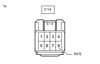
*a Front view of wire harness connector
(to Vehicle Sound Switch)
Disconnect the vehicle sound switch connector.
-
Measure the voltage according to the value(s) in the table below.
Standard Voltage Tester Connection Switch Condition Specified Condition I114-8 (NVS) - Body ground Engine switch on (IG) 11 to 14 V I114-8 (NVS) - Body ground Engine switch off Below 1 V Result Proceed to OK NG
NG
REPAIR OR REPLACE HARNESS OR CONNECTOR
OK
-
-
CHECK HARNESS AND CONNECTOR (VEHICLE SOUND SWITCH - STEREO COMPONENT EQUALIZER ASSEMBLY)
-
Disconnect the I114 vehicle sound switch connector.
-
Disconnect the I117 stereo component equalizer assembly connector.
-
Measure the resistance according to the value(s) in the table below.
Standard Resistance Tester Connection Condition Specified Condition I114-3 (NVI) - I117-5 (VLSW) Always Below 1 Ω I114-6 (NVM) - I117-14 (VSLI) Always Below 1 Ω I114-3 (NVI) or I117-5 (VLSW) - Body ground Always 10 kΩ or higher I114-6 (NVM) or I117-14 (VSLI) - Body ground Always 10 kΩ or higher Result Proceed to OK NG
OK
REPLACE STEREO COMPONENT EQUALIZER ASSEMBLY Click here
NG
REPAIR OR REPLACE HARNESS OR CONNECTOR
-