AUDIO AND VISUAL SYSTEM(for 8 Inch Display) AVC-LAN Circuit
DESCRIPTION
Each audio system component connected to the AVC-LAN (communication bus) transfers switch signals using the audio visual communication local area network.
If a short to +B or short to ground occurs in the AVC-LAN, the audio system will not function normally because communication is not possible.
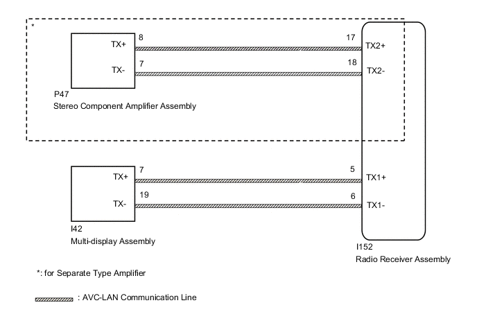
WIRING DIAGRAM
CAUTION / NOTICE / HINT
Note
When replacing the radio receiver assembly, always replace it with a new one.
If a radio receiver assembly which was installed to another vehicle is used, the following may occur:
-
A communication malfunction DTC may be stored.
-
The radio receiver assembly may not operate normally.
Tech Tips
Depending on the parts that are replaced during vehicle inspection or maintenance, performing initialization, registration or calibration may be needed. Refer to Precaution for Audio and Visual System.
PROCEDURE
-
INSPECT RADIO RECEIVER ASSEMBLY
-
Remove the radio receiver assembly.
-
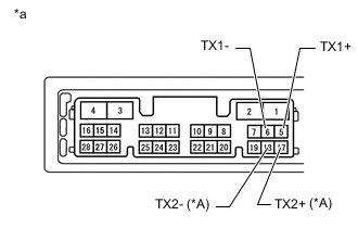
*A for Separate Type Amplifier *a Component without harness connected
(Radio Receiver Assembly)
Measure the resistance according to the value(s) in the table below.
Standard Resistance *: for Separate Type AmplifierTester Connection Condition Specified Condition 5 (TX1+) - 6 (TX1-) Always 60 to 80 Ω 17 (TX2+) - 18 (TX2-)* Always 60 to 80 Ω
Result Proceed to OK NG
NG 
REPLACE RADIO RECEIVER ASSEMBLY Click here
OK 
-
-
CHECK HARNESS AND CONNECTOR (AVC-LAN CIRCUIT)
-
Disconnect the I152 radio receiver assembly connector.
-
Disconnect the P47 stereo component amplifier assembly connector.*
-
*: for Separate Type Amplifier
-
-
Disconnect the I42 multi-display assembly connector.
-
Measure the resistance according to the value(s) in the table below.
Standard Resistance *: for Separate Type AmplifierTester Connection Condition Specified Condition I152-17 (TX2+) - P47-8 (TX+)* Always Below 1 Ω I152-18 (TX2-) - P47-7 (TX-)* Always Below 1 Ω I152-5 (TX1+) - I42-7 (TX+) Always Below 1 Ω I152-6 (TX1-) - I42-19 (TX-) Always Below 1 Ω I152-17 (TX2+) - Body ground* Always 10 kΩ or higher I152-18 (TX2-) - Body ground* Always 10 kΩ or higher I152-5 (TX1+) - Body ground Always 10 kΩ or higher I152-6 (TX1-) - Body ground Always 10 kΩ or higher
Result Proceed to OK NG
NG
REPAIR OR REPLACE HARNESS OR CONNECTOR
OK
-
-
INSPECT MALFUNCTIONING PARTS
-
Disconnect and reconnect each slave unit one by one until the master unit returns to normal operation.
Tech Tips
-
Check all slave units.
-
When disconnecting a slave unit causes the master unit to return to normal operation, this indicates that the slave unit is malfunctioning. Replace the malfunctioning slave unit.
OK Master unit returns to normal operation. Result Proceed to OK NG -
OK
REPLACE MALFUNCTIONING PARTS
NG
REPLACE RADIO RECEIVER ASSEMBLY Click here
-