AUDIO AND VISUAL SYSTEM(for 8 Inch Display), Diagnostic DTC:B15C0, B15C1
| DTC Code | DTC Name |
|---|---|
| B15C0 | Short in GPS Antenna |
| B15C1 | Open in GPS Antenna |
DESCRIPTION
These DTCs are stored when a malfunction occurs in the GPS antenna assembly.
| DTC No. | Detection Item | DTC Detection Condition | Trouble Area |
|---|---|---|---|
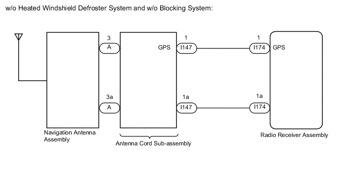
| B15C0 | Short in GPS Antenna | Navigation antenna error | w/o Heated Windshield Defroster System and w/o Blocking System:
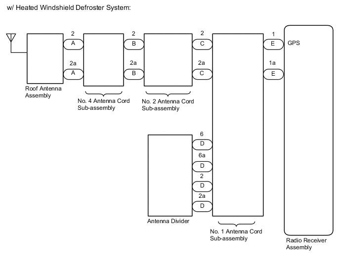
w/ Heated Windshield Defroster System:
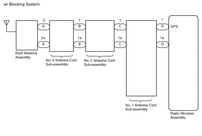
w/ Blocking System:
|
| B15C1 | Open in GPS Antenna | Error of the power source to the navigation antenna | w/o Heated Windshield Defroster System and w/o Blocking System:
w/ Heated Windshield Defroster System:
w/ Blocking System:
|
WIRING DIAGRAM
CAUTION / NOTICE / HINT
Note
When replacing the radio receiver assembly, always replace it with a new one.
If a radio receiver assembly which was installed to another vehicle is used, the following may occur:
-
A communication malfunction DTC may be stored.
-
The radio receiver assembly may not operate normally.
Tech Tips
Depending on the parts that are replaced during vehicle inspection or maintenance, performing initialization, registration or calibration may be needed. Refer to Precaution for Audio and Visual System.
PROCEDURE
-
CHECK DTC
-
Clear the DTCs.
Body Electrical > Navigation System > Clear DTCs -
Recheck for DTCs and check that no DTCs are output.
Body Electrical > Navigation System > Trouble CodesOK No DTCs are output. Result Proceed to OK NG
OK 
USE SIMULATION METHOD TO CHECK Click here
NG 
-
-
CHECK VEHICLE TYPE
-
Check the vehicle type.
Result Result Proceed to w/o Heated Windshield Defroster System and w/o Blocking System: A w/ Heated Windshield Defroster System B w/ Blocking System C
B 
INSPECT ANTENNA DIVIDER Click here
C
CHECK NO. 4 ANTENNA CORD SUB-ASSEMBLY Click here
A
-
-
INSPECT NAVIGATION ANTENNA ASSEMBLY
-
Remove the navigation antenna assembly.
-
Inspect the navigation antenna assembly.
Result Proceed to OK NG
NG
REPLACE NAVIGATION ANTENNA ASSEMBLY Click here
OK
-
-
CHECK ANTENNA CORD SUB-ASSEMBLY
-
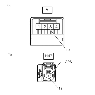
*a Front view of wire harness connector
(to Navigation Antenna Assembly)
*b Front view of wire harness connector
(to Wire Harness)
Disconnect the antenna connector from the navigation antenna assembly.
-
Disconnect the antenna connector from the wire harness.
-
Measure the resistance according to the value(s) in the table below.
Standard Resistance Tester Connection Condition Specified Condition A-3 - I147-1 (GPS) Always Below 1 Ω A-3a - I147-1a Always Below 1 Ω A-3 - Body ground Always 10 kΩ or higher A-3a - Body ground Always 10 kΩ or higher Result Proceed to OK NG
NG
REPLACE ANTENNA CORD SUB-ASSEMBLY Click here
OK
-
-
CHECK HARNESS AND CONNECTOR (ANTENNA CORD SUB-ASSEMBLY - RADIO RECEIVER ASSEMBLY)
-
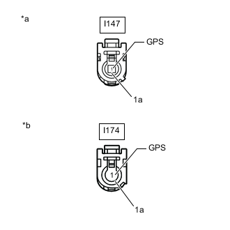
*a Front view of wire harness connector
(to Antenna Cord Sub-assembly)
*b Front view of wire harness connector
(to Radio Receiver Assembly)
Disconnect the antenna cord sub-assembly connector.
-
Disconnect the radio receiver assembly connector.
-
Measure the resistance according to the value(s) in the table below.
Standard Resistance Tester Connection Condition Specified Condition I147-1 (GPS) - I174-1 (GPS) Always Below 1 Ω I147-1a - I174-1a Always Below 1 Ω I147-1 (GPS) - Body ground Always 10 kΩ or higher I147-1a - Body ground Always 10 kΩ or higher Result Proceed to OK NG
OK
REPLACE RADIO RECEIVER ASSEMBLY Click here
NG
REPAIR OR REPLACE HARNESS OR CONNECTOR
-
-
INSPECT ANTENNA DIVIDER
-
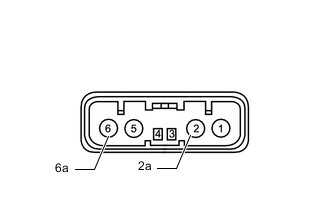
Remove the antenna divider.
-
Measure the resistance according to the value(s) in the table below.
Standard Resistance Tester Connection Condition Specified Condition 6 - 2 Always 10 kΩ or higher 2 - 2a Always 243 to 267 Ω 6 - 6a Always 10 kΩ or higher Result Proceed to OK NG
NG
REPLACE ANTENNA DIVIDER Click here
OK
-
-
CHECK NO. 4 ANTENNA CORD SUB-ASSEMBLY
-
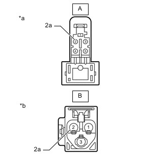
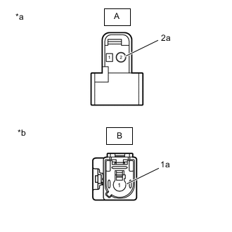
*a Front view of wire harness connector
(to Roof Antenna Assembly)
*b Front view of wire harness connector
(to No. 2 Antenna Cord Sub-assembly)
Disconnect the antenna connector from the roof antenna assembly.
-
Disconnect the antenna connector from No. 2 antenna cord sub-assembly.
-
Measure the resistance according to the value(s) in the table below.
Standard Resistance Tester Connection Condition Specified Condition A-2 - B-2 Always Below 1 Ω A-2a - B-2a Always Below 1 Ω A-2 - Body ground Always 10 kΩ or higher A-2a - Body ground Always 10 kΩ or higher Result Proceed to OK NG
NG
REPLACE NO. 4 ANTENNA CORD SUB-ASSEMBLY Click here
OK
-
-
CHECK NO. 2 ANTENNA CORD SUB-ASSEMBLY
-
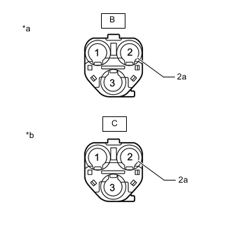
*a Front view of wire harness connector
(to No. 4 Antenna Cord Sub-assembly)
*b Front view of wire harness connector
(to No. 1 Antenna Cord Sub-assembly)
Disconnect the antenna connector from the No. 4 antenna cord sub-assembly.
-
Disconnect the antenna connector from No. 1 antenna cord sub-assembly.
-
Measure the resistance according to the value(s) in the table below.
Standard Resistance Tester Connection Condition Specified Condition B-2 - C-2 Always Below 1 Ω B-2a - C-2a Always Below 1 Ω B-2 - Body ground Always 10 kΩ or higher B-2a - Body ground Always 10 kΩ or higher Result Proceed to OK NG
NG
REPLACE NO. 2 ANTENNA CORD SUB-ASSEMBLY Click here
OK
-
-
CHECK NO. 1 ANTENNA CORD SUB-ASSEMBLY
-
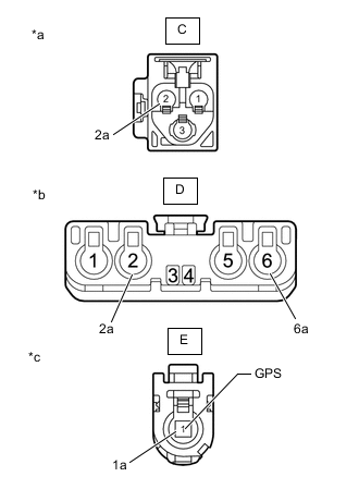
*a Front view of wire harness connector
(to No. 2 Antenna Cord Sub-assembly)
*b Front view of wire harness connector
(to Antenna Divider)
*c Front view of wire harness connector
(to Radio Receiver Assembly)
Disconnect the antenna connector from the No. 2 antenna cord sub-assembly.
-
Disconnect the antenna connector from the antenna divider.
-
Disconnect the antenna connector from the radio receiver assembly.
-
Measure the resistance according to the value(s) in the table below.
Standard Resistance Tester Connection Condition Specified Condition C-2 - D-6 Always Below 1 Ω C-2a - D-6a Always Below 1 Ω D-2 - E-1 (GPS) Always Below 1 Ω D-2a - E-1a Always Below 1 Ω C-2 - Body ground Always 10 kΩ or higher C-2a - Body ground Always 10 kΩ or higher D-2 - Body ground Always 10 kΩ or higher D-2a - Body ground Always 10 kΩ or higher Result Proceed to OK NG
NG
REPLACE NO. 1 ANTENNA CORD SUB-ASSEMBLY Click here
OK
-
-
REPLACE ANTENNA DIVIDER
-
Replace the antenna divider with a new or known good one.
Result Proceed to NEXT
NEXT
-
-
CHECK DTC
-
Clear the DTCs.
Body Electrical > Navigation System > Clear DTCs -
Recheck for DTCs and check that no DTCs are output.
Body Electrical > Navigation System > Trouble CodesOK No DTCs are output. Result Proceed to OK NG
OK
END (ANTENNA DIVIDER IS DEFECTIVE)
NG
-
-
REPLACE ROOF ANTENNA ASSEMBLY
-
Replace the roof antenna assembly with a new or known good one.
Result Proceed to NEXT
NEXT
-
-
CHECK DTC
-
Clear the DTCs.
Body Electrical > Navigation System > Clear DTCs -
Recheck for DTCs and check that no DTCs are output.
Body Electrical > Navigation System > Trouble CodesOK No DTCs are output. Result Proceed to OK NG
OK
END (ROOF ANTENNA ASSEMBLY IS DEFECTIVE)
NG
REPLACE RADIO RECEIVER ASSEMBLY Click here
-
-
CHECK NO. 4 ANTENNA CORD SUB-ASSEMBLY
-
*a Front view of wire harness connector
(to Roof Antenna Assembly)
*b Front view of wire harness connector
(to No. 2 Antenna Cord Sub-assembly)
Disconnect the antenna connector from the roof antenna assembly.
-
Disconnect the antenna connector from No. 2 antenna cord sub-assembly.
-
Measure the resistance according to the value(s) in the table below.
Standard Resistance Tester Connection Condition Specified Condition A-2 - B-1 Always Below 1 Ω A-2a - B-1a Always Below 1 Ω A-2 - Body ground Always 10 kΩ or higher A-2a - Body ground Always 10 kΩ or higher Result Proceed to OK NG
NG
REPLACE NO. 4 ANTENNA CORD SUB-ASSEMBLY Click here
OK
-
-
CHECK NO. 2 ANTENNA CORD SUB-ASSEMBLY
-
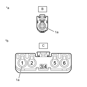
*a Front view of wire harness connector
(to No. 4 Antenna Cord Sub-assembly)
*b Front view of wire harness connector
(to No. 1 Antenna Cord Sub-assembly)
Disconnect the antenna connector from the No. 4 antenna cord sub-assembly.
-
Disconnect the antenna connector from No. 1 antenna cord sub-assembly.
-
Measure the resistance according to the value(s) in the table below.
Standard Resistance Tester Connection Condition Specified Condition B-1 - C-1 Always Below 1 Ω B-1a - C-1a Always Below 1 Ω B-1 - Body ground Always 10 kΩ or higher B-1a - Body ground Always 10 kΩ or higher Result Proceed to OK NG
NG
REPLACE NO. 2 ANTENNA CORD SUB-ASSEMBLY Click here
OK
-
-
CHECK NO. 1 ANTENNA CORD SUB-ASSEMBLY
-
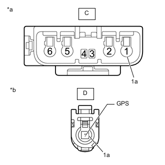
*a Front view of wire harness connector
(to No. 2 Antenna Cord Sub-assembly)
*c Front view of wire harness connector
(to Radio Receiver Assembly)
Disconnect the antenna connector from the No. 2 antenna cord sub-assembly.
-
Disconnect the antenna connector from the radio receiver assembly.
-
Measure the resistance according to the value(s) in the table below.
Standard Resistance Tester Connection Condition Specified Condition C-1 - D-1 (GPS) Always Below 1 Ω C-1a - D-1a Always Below 1 Ω C-1 - Body ground Always 10 kΩ or higher C-1a - Body ground Always 10 kΩ or higher Result Proceed to OK NG
NG
REPLACE NO. 1 ANTENNA CORD SUB-ASSEMBLY Click here
OK
-
-
REPLACE ROOF ANTENNA ASSEMBLY
-
Replace the roof antenna assembly with a new or known good one.
Result Proceed to NEXT
NEXT
-
-
CHECK DTC
-
Clear the DTCs.
Body Electrical > Navigation System > Clear DTCs -
Recheck for DTCs and check that no DTCs are output.
Body Electrical > Navigation System > Trouble CodesOK No DTCs are output. Result Proceed to OK NG
OK
END (ROOF ANTENNA ASSEMBLY IS DEFECTIVE)
NG
REPLACE RADIO RECEIVER ASSEMBLY Click here
-