AUDIO AND VISUAL SYSTEM(for 10.3 Inch Display) Pointer Displayed/not Displayed Repeatedly
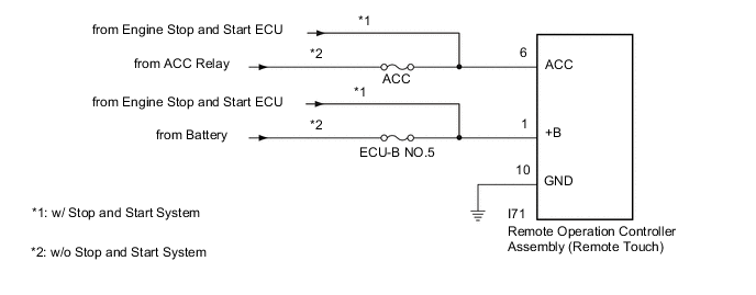
WIRING DIAGRAM
CAUTION / NOTICE / HINT
Note
-
Inspect the fuses for circuits related to this system before performing the following procedure.
-
When replacing the radio receiver assembly or navigation ECU, always replace it with a new one.
If a radio receiver assembly or navigation ECU which was installed to another vehicle is used, the following may occur:
-
A communication malfunction DTC may be stored.
-
The radio receiver assembly or navigation ECU may not operate normally.
Tech Tips
Depending on the parts that are replaced during vehicle inspection or maintenance, performing initialization, registration or calibration may be needed. Refer to Precaution for Audio and Visual System.
PROCEDURE
-
CONFIRM SYMPTOMS
-
Recheck the situation when the malfunction occurs.
Tech Tips
-
When a hand is rested on the remote touch screen while driving, the remote touch may react to finger movements and repeatedly display and hide the pointer.
-
When accelerating excessively on rough roads, the remote touch may react to the acceleration and repeatedly display and hide the pointer.
Result Result Proceed to Symptom occurs in any situation. A Symptom occurs when hand is rested on the remote touch screen while driving. B Symptom occurs when accelerating excessively on rough roads. C -
B 
END
C 
CHECK CONNECTOR CONNECTION CONDITION Click here
A 
-
-
CHECK FOR FOREIGN MATTER
-
Check if there is any foreign matter around the remote touch screen that interferes with operation of the screen.
OK There is no foreign matter around the remote touch screen that interferes with operation of the screen. Result Proceed to OK NG
NG
REMOVE FOREIGN MATTER (CHECK OPERATION AGAIN)
OK
-
-
REMOTE TOUCH SELF CHECK (CHECK TOUCH SCREEN OPERATION POSITION RECOGNITION CONDITION)
-
Enter self-diagnostic mode.
-
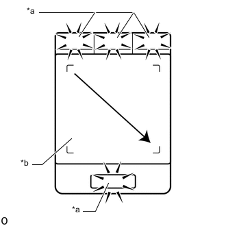
*a Switch Illumination *b Touch Screen Operate the remote touch screen diagonally from the upper left to the lower right and check that the brightness of the switch illumination changes.
Note
Since the remote touch screen may recognize a pinch in/out operation if operated with 2 fingers, always use 1 finger to operate the remote touch in self-diagnostic mode.
OK Brightness changes according to touch screen operation. Result Result Proceed to Brightness of the switch illumination changes according to remote touch screen operation. A Brightness of the switch illumination does not change according to remote touch screen operation. B Switch illumination continues to blink. Tech Tips
When the switch illumination blinks, the remote touch has stored a DTC.
B
REPLACE REMOTE OPERATION CONTROLLER ASSEMBLY (REMOTE TOUCH) Click here
A
-
-
REPLACE NAVIGATION ECU
-
Replace the navigation ECU with a new one.
-
Check the malfunction disappears.
OK Malfunction disappears. Result Proceed to OK NG
OK
END (NAVIGATION ECU IS DEFECTIVE)
NG
REPLACE RADIO RECEIVER ASSEMBLY Click here
-
-
CHECK CONNECTOR CONNECTION CONDITION
-
Check if the P69 remote operation controller assembly (remote touch) connector is securely connected.
OK The connector is securely connected. Result Proceed to OK NG
NG
SECURELY CONNECTED
OK
-
-
CHECK HARNESS AND CONNECTOR (REMOTE OPERATION CONTROLLER ASSEMBLY [REMOTE TOUCH] - BATTERY AND BODY GROUND)
-
Disconnect the remote operation controller assembly (remote touch) connector.
-
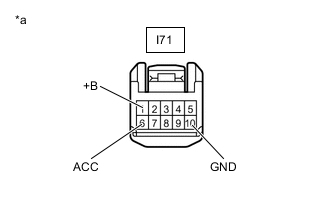
*a Front view of wire harness connector
(to Remote Operation Controller Assembly [Remote Touch])
Measure the resistance according to the value(s) in the table below.
Standard Resistance Tester Connection Condition Specified Condition I71-10 (GND) - Body ground Always Below 1 Ω -
Measure the voltage according to the value(s) in the table below.
Standard Voltage *1: w/o Stop and Start SystemTester Connection Condition Specified Condition I71-1 (+B) - Body ground Always 11 to 14 V*1
10.5 to 16 V*2
I71-6 (ACC) - Body ground Engine switch on (ACC) 11 to 14 V*1
10.5 to 16 V*2
*2: w/ Stop and Start System
Result Proceed to OK NG
OK
REPLACE REMOTE OPERATION CONTROLLER ASSEMBLY (REMOTE TOUCH) Click here
NG
REPAIR OR REPLACE HARNESS OR CONNECTOR
-