AUDIO AND VISUAL SYSTEM(except 8 Speakers) Radio Receiver Power Source Circuit
DESCRIPTION
This is the power source circuit to operate the radio receiver assembly.
WIRING DIAGRAM
-
w/ Stop and Start System
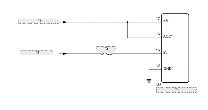
*1 from Eco Run Vehicle Converter Assembly *2 ECI-IG NO.2 *3 from IG1 NO.2 Relay *4 Radio Receiver Assembly -
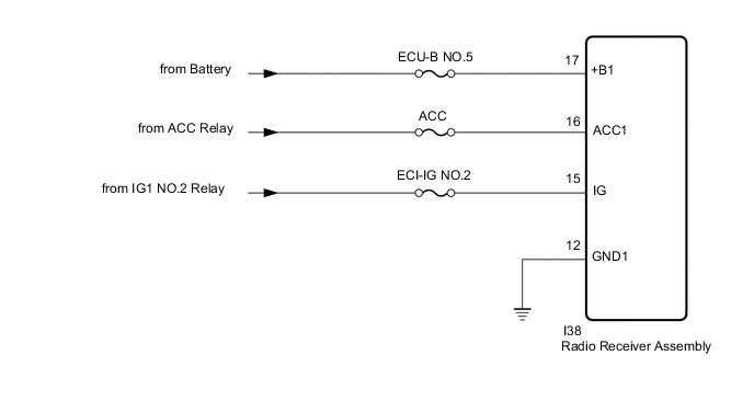
w/o Stop and Start System
CAUTION / NOTICE / HINT
Note
Inspect the fuses for circuits related to this system before performing the following procedure.
PROCEDURE
-
CHECK HARNESS AND CONNECTOR (RADIO RECEIVER ASSEMBLY - BATTERY AND BODY GROUND)
-
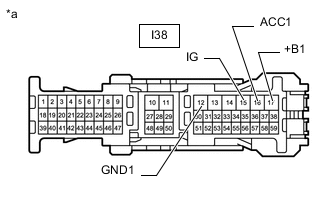
*a Front view of wire harness connector
(to Radio Receiver Assembly)
Disconnect the radio receiver assembly connector.
-
Measure the resistance according to the value(s) in the table below.
Standard Resistance Tester Connection Condition Specified Condition I38-12 (GND1) - Body ground Always Below 1 Ω -
Measure the voltage according to the value(s) in the table below.
Standard Voltage w/ Stop and Start System Tester Connection Condition Specified Condition I38-17 (+B1) - I38-12 (GND1) Always 10.5 to 16 V I38-16 (ACC1) - I38-12 (GND1) Engine switch on (ACC) 10.5 to 16 V I38-15 (IG) - I38-12 (GND1) Engine switch on (IG) 11 to 14 V w/o Stop and Start System Tester Connection Condition Specified Condition I38-17 (+B1) - I38-12 (GND1) Always 11 to 14 V I38-16 (ACC1) - I38-12 (GND1) Engine switch on (ACC) 11 to 14 V I38-15 (IG) - I38-12 (GND1) Engine switch on (IG) 11 to 14 V Result Proceed to OK NG
OK 
PROCEED TO NEXT SUSPECTED AREA SHOWN IN PROBLEM SYMPTOMS TABLE Click here
NG
REPAIR OR REPLACE HARNESS OR CONNECTOR
-