AUDIO AND VISUAL SYSTEM(except 8 Speakers), Diagnostic DTC:B157D
| DTC Code | DTC Name |
|---|---|
| B157D | DAB Tuner Antenna Disconnected |
DESCRIPTION
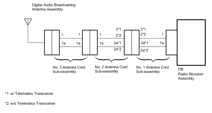
This DTC is stored when a malfunction occurs in the digital audio broadcasting antenna assembly which is connected to the radio receiver assembly.
| DTC No. | Detection Item | DTC Detection Condition | Trouble Area |
|---|---|---|---|
| B157D | DAB Tuner Antenna Disconnected | The digital audio broadcasting antenna assembly is not connected |
|
WIRING DIAGRAM
CAUTION / NOTICE / HINT
Note
Depending on the parts that are replaced during vehicle inspection or maintenance, performing initialization, registration or calibration may be needed. Refer to precaution for audio and visual system.
PROCEDURE
-
CHECK CONNECTION OF DIGITAL AUDIO BROADCASTING ANTENNA CABLE
-
Check if the digital audio broadcasting antenna assembly cable is securely connected to the radio receiver assembly.
OK Digital audio broadcasting antenna assembly cable is securely connected Result Proceed to OK NG
NG 
SECURELY CONNECT DAB RADIO ANTENNA CABLE
OK 
-
-
CONFIRM MODEL
-
Choose the model to be inspected.
Model Model Proceed to w/ Telematics Transceiver A w/o Telematics Transceiver B
B 
CHECK NO. 1 ANTENNA CORD SUB-ASSEMBLY Click here
A
-
-
CHECK NO. 1 ANTENNA CORD SUB-ASSEMBLY
-
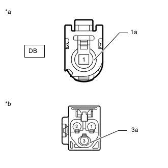
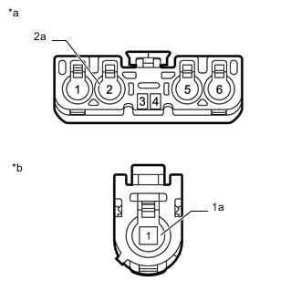
*a Front view of wire harness connector
(to Radio Receiver Assembly)
*b Front view of wire harness connector
(to No. 2 Antenna Cord Sub-assembly)
Disconnect the antenna connector from the radio receiver assembly.
-
Disconnect the antenna connector from the No. 2 antenna cord sub-assembly.
-
Measure the resistance according to the value(s) in the table below.
Standard Resistance Tester Connection Condition Specified Condition DB-1 - 3 Always Below 1 Ω DB-1a - 3a Always Below 1 Ω DB-1 - Body ground Always 10 kΩ or higher DB-1a - Body ground Always 10 kΩ or higher Result Proceed to OK NG
NG
REPLACE NO. 1 ANTENNA CORD SUB-ASSEMBLY Click here
OK
-
-
CHECK NO. 2 ANTENNA CORD SUB-ASSEMBLY
-
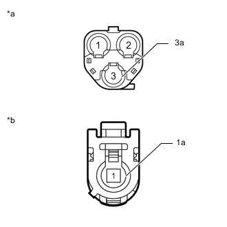
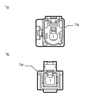
*a Front view of wire harness connector
(to No. 1 Antenna Cord Sub-assembly)
*b Front view of wire harness connector
(to No. 3 Antenna Cord Sub-assembly)
Disconnect the antenna connector from the No. 1 antenna cord sub-assembly.
-
Disconnect the antenna connector from the No. 3 antenna cord sub-assembly.
-
Measure the resistance according to the value(s) in the table below.
Standard Resistance Tester Connection Condition Specified Condition 3 - 1 Always Below 1 Ω 3a - 1a Always Below 1 Ω 3 - Body ground Always 10 kΩ or higher 3a - Body ground Always 10 kΩ or higher Result Proceed to OK NG
OK
GO TO STEP 7 Click here
NG
REPLACE NO. 2 ANTENNA CORD SUB-ASSEMBLY Click here
-
-
CHECK NO. 1 ANTENNA CORD SUB-ASSEMBLY
-
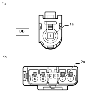
*a Front view of wire harness connector
(to Radio Receiver Assembly)
*b Front view of wire harness connector
(to No. 2 Antenna Cord Sub-assembly)
Disconnect the antenna connector from the radio receiver assembly.
-
Disconnect the antenna connector from the No. 2 antenna cord sub-assembly.
-
Measure the resistance according to the value(s) in the table below.
Standard Resistance Tester Connection Condition Specified Condition DB-1 - 2 Always Below 1 Ω DB-1a - 2a Always Below 1 Ω DB-1 - Body ground Always 10 kΩ or higher DB-1a - Body ground Always 10 kΩ or higher Result Proceed to OK NG
NG
REPLACE NO. 1 ANTENNA CORD SUB-ASSEMBLY Click here
OK
-
-
CHECK NO. 2 ANTENNA CORD SUB-ASSEMBLY
-
*a Front view of wire harness connector
(to No. 1 Antenna Cord Sub-assembly)
*b Front view of wire harness connector
(to No. 3 Antenna Cord Sub-assembly)
Disconnect the antenna connector from the No. 1 antenna cord sub-assembly.
-
Disconnect the antenna connector from the No. 3 antenna cord sub-assembly.
-
Measure the resistance according to the value(s) in the table below.
Standard Resistance Tester Connection Condition Specified Condition 2 - 1 Always Below 1 Ω 2a - 1a Always Below 1 Ω 2 - Body ground Always 10 kΩ or higher 2a - Body ground Always 10 kΩ or higher Result Proceed to OK NG
NG
REPLACE NO. 2 ANTENNA CORD SUB-ASSEMBLY Click here
OK
-
-
CHECK NO. 3 ANTENNA CORD SUB-ASSEMBLY
-
*a Front view of wire harness connector
(to No. 2 Antenna Cord Sub-assembly)
*b Front view of wire harness connector
(to Digital Audio Broadcasting Antenna Assembly)
Disconnect the antenna connector from the No. 2 antenna cord sub-assembly.
-
Disconnect the antenna connector from the digital audio broadcasting antenna assembly.
-
Measure the resistance according to the value(s) in the table below.
Standard Resistance Tester Connection Condition Specified Condition 1 - 1 Always Below 1 Ω 1a - 1a Always Below 1 Ω 1 - Body ground Always 10 kΩ or higher 1a - Body ground Always 10 kΩ or higher Result Proceed to OK NG
NG
REPLACE NO. 3 ANTENNA CORD SUB-ASSEMBLY Click here
OK
-
-
CHECK DIGITAL AUDIO BROADCASTING ANTENNA ASSEMBLY
-
Replace the digital audio broadcasting antenna assembly.
-
Clear the DTCs.
Body Electrical > Navigation System > Clear DTCs -
Recheck for DTCs and check that no DTCs are output.
Body Electrical > Navigation System > Trouble CodesOK No DTCs are output. Result Proceed to OK NG
OK
END (DIGITAL AUDIO BROADCASTING ANTENNA ASSEMBLY IS DEFECTIVE)
NG
REPLACE RADIO RECEIVER ASSEMBLY Click here
-