AUDIO AND VISUAL SYSTEM(except 8 Speakers), Diagnostic DTC:B158F
| DTC Code | DTC Name |
|---|---|
| B158F | AV Signal Stoppage (Low Battery Voltage) |
DESCRIPTION
This DTC is stored when a video or audio signal is interrupted due to battery voltage input to the radio receiver assembly dropping temporarily.
| DTC No. | Detection Item | DTC Detection Condition | Trouble Area |
|---|---|---|---|
| B158F | AV Signal Stoppage (Low Battery Voltage) | A video or audio signal is interrupted when the battery voltage drops |
|
WIRING DIAGRAM
-
w/ Stop and Start System
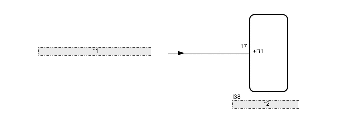
*1 from Eco Run Vehicle Converter Assembly *2 Radio Receiver Assembly -
w/o Stop and Start System
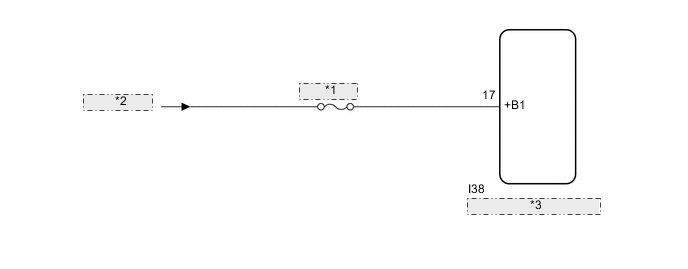
*1 ECU-B NO.5 *2 from Battery *3 Radio Receiver Assembly
CAUTION / NOTICE / HINT
Note
-
Inspect the fuses for circuits related to this system before performing the following inspection procedure.
-
Depending on the parts that are replaced during vehicle inspection or maintenance, performing initialization, registration or calibration may be needed. Refer to precaution for audio and visual system.
PROCEDURE
-
CHECK VEHICLE SIGNAL (OPERATION CHECK)
-
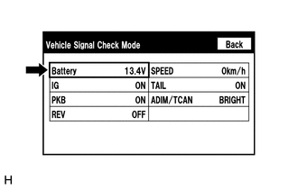
Enter the "Vehicle Signal Check Mode" screen. Refer to Check Vehicle Signal in Operation Check.
-
Measure the battery voltage.
Standard voltage 11 to 14 V Tech Tips
This display is updated once per second. As a result, it is normal for the display to lag behind the actual switch operation.
Result Proceed to OK NG
NG 
CHECK HARNESS AND CONNECTOR (RADIO RECEIVER ASSEMBLY - BATTERY) Click here
OK 
-
-
CHECK DTC
-
Clear the DTCs.
Body Electrical > Navigation System > Clear DTCs -
Recheck for DTCs and check that no DTCs are output.
Body Electrical > Navigation System > Trouble CodesOK No DTCs are output. Result Proceed to OK NG
OK 
USE SIMULATION METHOD TO CHECK Click here
NG
REPLACE RADIO RECEIVER ASSEMBLY Click here
-
-
CHECK HARNESS AND CONNECTOR (RADIO RECEIVER ASSEMBLY - BATTERY)
-
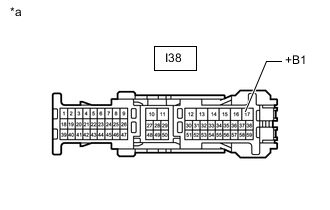
*a Front view of wire harness connector
(to Radio Receiver Assembly)
Disconnect the radio receiver assembly connector.
-
Measure the voltage according to the value(s) in the table below.
Standard Voltage w/ Stop and Start System Tester Connection Condition Specified Condition I38-17 (+B1) - Body ground Always 10.5 to 16 V w/o Stop and Start System Tester Connection Condition Specified Condition I38-17 (+B1) - Body ground Always 11 to 14 V Result Proceed to OK NG
OK
REPLACE RADIO RECEIVER ASSEMBLY Click here
NG
REPAIR OR REPLACE HARNESS OR CONNECTOR
-