AUDIO AND VISUAL SYSTEM(except 8 Speakers), Diagnostic DTC:B15C0, B15C1
| DTC Code | DTC Name |
|---|---|
| B15C0 | Short in GPS Antenna |
| B15C1 | Open in GPS Antenna |
DESCRIPTION
-
*1: w/o Digital TV Function
*2: w/ Digital TV Function
These DTCs are stored when a malfunction occurs in the navigation antenna assembly*1 or roof antenna assembly*2.
| DTC No. | Detection Item | DTC Detection Condition | Trouble Area |
|---|---|---|---|
| B15C0 | Short in GPS Antenna | Navigation antenna assembly*1 or roof antenna assembly*2 malfunction |
|
| B15C1 | Open in GPS Antenna | Navigation antenna assembly*1 or roof antenna assembly*2 power source malfunction |
|
WIRING DIAGRAM
-
w/o Digital TV Function
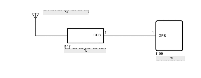
*a Navigation Antenna Assembly *b Antenna Cord Sub-assembly *c Radio Receiver Assembly -
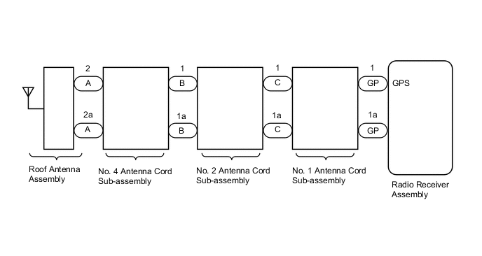
w/ Digital TV Function
CAUTION / NOTICE / HINT
Note
Depending on the parts that are replaced during vehicle inspection or maintenance, performing initialization, registration or calibration may be needed. Refer to precaution for audio and visual system.
PROCEDURE
-
CHECK DTC
-
Clear the DTCs.
Body Electrical > Navigation System > Clear DTCs -
Recheck for DTCs and check that no DTCs are output.
Body Electrical > Navigation System > Trouble CodesOK No DTCs are output. Result Proceed to OK NG
OK 
USE SIMULATION METHOD TO CHECK Click here
NG 
-
-
CHECK VEHICLE TYPE
-
Check the vehicle type.
Result Result Proceed to w/o Digital TV Function A w/ Digital TV Function B
B 
INSPECT ROOF ANTENNA ASSEMBLY Click here
A
-
-
CHECK CONNECTION OF NAVIGATION ANTENNA ASSEMBLY
-
Check if the navigation antenna assembly is securely connected to the radio receiver assembly.
OK Navigation antenna assembly is securely connected. Result Proceed to OK NG
NG
SECURELY CONNECT NAVIGATION ANTENNA ASSEMBLY
OK
-
-
INSPECT NAVIGATION ANTENNA ASSEMBLY
-
Remove the navigation antenna assembly.
-
Inspect the navigation antenna assembly.
Result Proceed to OK NG
NG
REPLACE NAVIGATION ANTENNA ASSEMBLY Click here
OK
-
-
INSPECT ANTENNA CORD SUB-ASSEMBLY
-
Remove the antenna cord sub-assembly.
-
Inspect the antenna cord sub-assembly.
Result Proceed to OK NG
NG
REPLACE ANTENNA CORD SUB-ASSEMBLY Click here
OK
-
-
CHECK HARNESS AND CONNECTOR (RADIO RECEIVER ASSEMBLY - ANTENNA CORD SUB-ASSEMBLY)
-
Disconnect the I109 radio receiver assembly connector.
-
Disconnect the I147 antenna cord sub-assembly connector.
-
Measure the resistance according to the value(s) in the table below.
Standard Resistance Tester Connection Condition Specified Condition I109-1 (GPS) - I147-1 (GPS) Always Below 1 Ω I109-1 (GPS) or I147-1 (GPS) - Body ground Always 10 kΩ or higher Result Proceed to OK NG
OK
REPLACE RADIO RECEIVER ASSEMBLY Click here
NG
REPAIR OR REPLACE HARNESS OR CONNECTOR
-
-
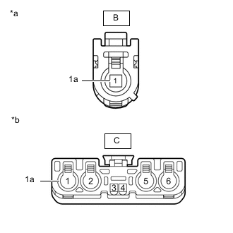
INSPECT ROOF ANTENNA ASSEMBLY
-
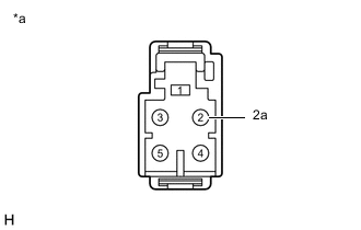
*a Roof Antenna Assembly Remove the roof antenna assembly.
-
Measure the resistance according to the value(s) in the table below.
Standard Resistance Tester Connection Condition Specified Condition 2 - 2a Always 4 to 11 kΩ Result Proceed to OK NG
NG
REPLACE ROOF ANTENNA ASSEMBLY Click here
OK
-
-
INSPECT NO. 4 ANTENNA CORD SUB-ASSEMBLY
-
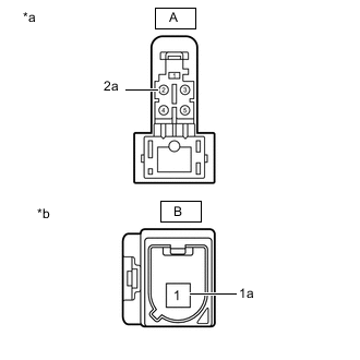
*a Front view of wire harness connector
(to Roof Antenna Assembly)
*b Front view of wire harness connector
(to No. 2 Antenna Cord Sub-assembly)
Disconnect the antenna connector from the roof antenna assembly connector.
-
Disconnect the antenna connector from the No. 2 antenna cord sub-assembly connector.
-
Measure the resistance according to the value(s) in the table below.
Standard Resistance Tester Connection Condition Specified Condition A-2 - B-1 Always Below 1 Ω A-2a - B-1a Always Below 1 Ω A-2 - Body ground Always 10 kΩ or higher A-2a - Body ground Always 10 kΩ or higher Result Proceed to OK NG
NG
REPLACE NO. 4 ANTENNA CORD SUB-ASSEMBLY Click here
OK
-
-
INSPECT NO. 2 ANTENNA CORD SUB-ASSEMBLY
-
*a Front view of wire harness connector
(to No. 4 Antenna Cord Sub-assembly)
*b Front view of wire harness connector
(to No. 1 Antenna Cord Sub-assembly)
Disconnect the antenna connector from the No. 4 antenna cord sub-assembly connector.
-
Disconnect the antenna connector from the No. 1 antenna cord sub-assembly connector.
-
Measure the resistance according to the value(s) in the table below.
Standard Resistance Tester Connection Condition Specified Condition B-1 - C-1 Always Below 1 Ω B-1a - C-1a Always Below 1 Ω B-1 - Body ground Always 10 kΩ or higher B-1a - Body ground Always 10 kΩ or higher Result Proceed to OK NG
NG
REPLACE NO. 2 ANTENNA CORD SUB-ASSEMBLY Click here
OK
-
-
INSPECT NO. 1 ANTENNA CORD SUB-ASSEMBLY
-
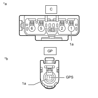
*a Front view of wire harness connector
(to No. 2 Antenna Cord Sub-assembly)
*b Front view of wire harness connector
(to Radio Receiver Assembly)
Disconnect the antenna connector from the No. 2 antenna cord sub-assembly connector.
-
Disconnect the antenna connector from the radio receiver assembly connector.
-
Measure the resistance according to the value(s) in the table below.
Standard Resistance Tester Connection Condition Specified Condition C-1 - GP-1 (GPS) Always Below 1 Ω C-1a - GP-1a Always Below 1 Ω C-1 - Body ground Always 10 kΩ or higher C-1a - Body ground Always 10 kΩ or higher Result Proceed to OK NG
OK
REPLACE RADIO RECEIVER ASSEMBLY Click here
NG
REPLACE NO. 1 ANTENNA CORD SUB-ASSEMBLY Click here
-