AUDIO AND VISUAL SYSTEM(except 8 Speakers) Display Signal Circuit between Multi-display and Radio Receiver
DESCRIPTION
The display image signal from the radio receiver assembly is sent to the multi-display assembly using a GVIF cable.
WIRING DIAGRAM
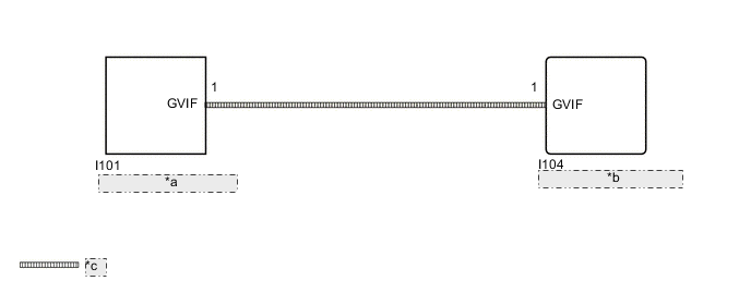
| *a | Multi-display Assembly |
| *b | Radio Receiver Assembly |
| *c | GVIF Cable |
PROCEDURE
-
CHECK GVIF CABLE CONNECTOR
-
Check if the GVIF cable connector between the radio receiver assembly and the multi-display assembly has any connection problems.
-
Check that the screen display is normal.
OK Screen display is normal. Result Proceed to OK NG
OK 
USE SIMULATION METHOD TO CHECK Click here
NG 
-
-
CHECK MULTI-DISPLAY ASSEMBLY
-
Replace the multi-display assembly.
-
Check that the screen display is normal.
OK Screen display is normal. Result Proceed to OK NG
OK
END (MULTI-DISPLAY ASSEMBLY IS DEFECTIVE)
NG
PROCEED TO NEXT SUSPECTED AREA SHOWN IN PROBLEM SYMPTOMS TABLE Click here
-