AUDIO AND VISUAL SYSTEM(for 8 Speakers) Switch Lights of Remote Touch do not Illuminate
DESCRIPTION
Power is supplied to the remote operation controller assembly when the light control switch is in the tail or head position.
Tech Tips
Only the "AUDIO", "MENU" and return switches on the remote operation controller assembly illuminate.
WIRING DIAGRAM
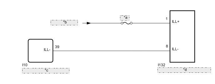
| *a | PANEL |
| *b | from TAIL Relay |
| *c | Combination Meter Assembly |
| *d | Remote Operation Controller Assembly |
CAUTION / NOTICE / HINT
Note
Inspect the fuses for circuits related to this system before performing the following procedure.
PROCEDURE
-
CHECK HARNESS AND CONNECTOR (ILLUMINATION SIGNAL)
-
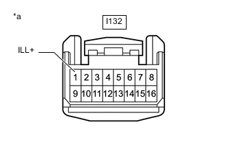
*a Front view of wire harness connector
(to Remote Operation Controller Assembly)
Disconnect the remote operation controller assembly connector.
-
Measure the voltage according to the value(s) in the table below.
Standard Voltage Tester Connection Switch Condition Specified Condition I132-1 (ILL+) - Body ground Light control switch in tail or head position 11 to 14 V Result Proceed to OK NG
NG 
REPAIR OR REPLACE HARNESS OR CONNECTOR
OK 
-
-
CHECK HARNESS AND CONNECTOR (REMOTE OPERATION CONTROLLER ASSEMBLY - COMBINATION METER ASSEMBLY)
-
Disconnect the I132 remote operation controller assembly connector.
-
Disconnect the I10 combination meter assembly connector.
-
Measure the resistance according to the value(s) in the table below.
Standard Resistance Tester Connection Condition Specified Condition I132-8 (ILL-) - I10-39 (ILL-) Always Below 1 Ω I132-8 (ILL-) or I10-39 (ILL-) - Body ground Always 10 kΩ or higher Result Proceed to OK NG
NG
REPAIR OR REPLACE HARNESS OR CONNECTOR
OK
-
-
CHECK REMOTE OPERATION CONTROLLER ASSEMBLY
-
Replace the remote operation controller assembly.
-
Check if the switch illumination turns on.
OK The switch illumination turns on when the light control switch is in the tail or head position. Result Proceed to OK NG
OK
END (REMOTE OPERATION CONTROLLER ASSEMBLY IS DEFECTIVE)
NG
GO TO METER / GAUGE SYSTEM Click here
-