AUDIO AND VISUAL SYSTEM(for 8 Speakers), Diagnostic DTC:B1567
| DTC Code | DTC Name |
|---|---|
| B1567 | HUD Disconnected |
DESCRIPTION
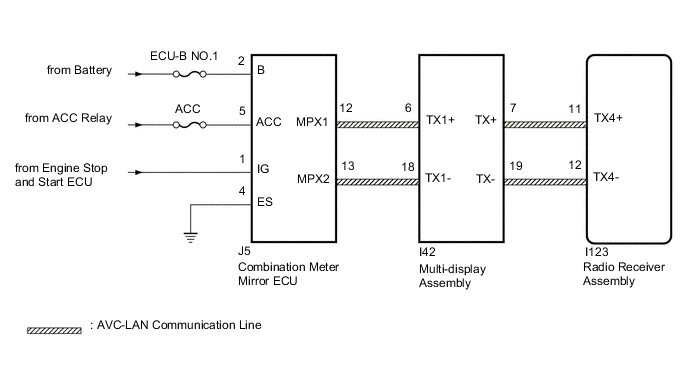
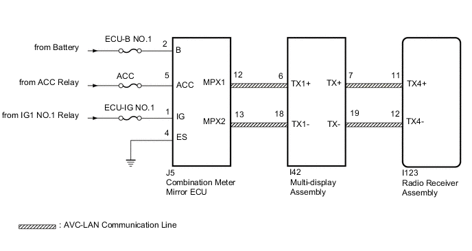
The multi-display and combination meter mirror ECU or multi-display and radio receiver assembly are connected by the AVC-LAN communication line. When an AVC-LAN communication error occurs between the combination meter mirror ECU and the radio receiver assembly, this DTC will be stored.
| DTC No. | Detection Item | DTC Detection Condition | Trouble Area |
|---|---|---|---|
| B1567 | HUD Disconnected | A device that is listed in the AVC-LAN connected device record of the master unit is missing. |
|
Tech Tips
For the AVC-LAN communication line, the radio receiver assembly is the master unit.
WIRING DIAGRAM
-
w/ Stop and Start System
-
w/o Stop and Start System
CAUTION / NOTICE / HINT
Note
Inspect the fuses for circuits related to this system before performing the following inspection procedure.
Tech Tips
w/ Stop and Start System:
The audio and visual system troubleshooting procedure is based on the premise that the stop and start system is operating normally. Check the stop and start system first before troubleshooting the audio and visual system.
PROCEDURE
-
CHECK DTC
-
Clear the DTCs.
Body Electrical > Navigation System > Clear DTCs -
Recheck for DTCs and check that no DTCs are output.
Body Electrical > Navigation System > Trouble CodesOK No DTCs are output. Result Proceed to OK NG
OK 
USE SIMULATION METHOD TO CHECK Click here
NG 
-
-
CHECK HARNESS AND CONNECTOR (COMBINATION METER MIRROR ECU - BATTERY AND BODY GROUND)
-
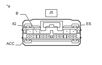
*a Front view of wire harness connector
(to Combination Meter Mirror ECU)
Disconnect the combination meter mirror ECU connector.
-
Measure the resistance according to the value(s) in the table below.
Standard Resistance Tester Connection Condition Specified Condition J5-4 (ES) - Body ground Always Below 1 Ω -
Measure the voltage according to the value(s) in the table below.
Standard Voltage w/ Stop and Start System Tester Connection Condition Specified Condition J5-1 (IG) - Body ground Engine switch on (IG) 10.5 to 16 V J5-2 (B) - Body ground Always 11 to 14 V J5-5 (ACC) - Body ground Engine switch on (ACC) 11 to 14 V w/o Stop and Start System Tester Connection Condition Specified Condition J5-1 (IG) - Body ground Engine switch on (IG) 11 to 14 V J5-2 (B) - Body ground Always 11 to 14 V J5-5 (ACC) - Body ground Engine switch on (ACC) 11 to 14 V Result Proceed to OK NG
NG
REPAIR OR REPLACE HARNESS OR CONNECTOR
OK
-
-
INSPECT RADIO RECEIVER ASSEMBLY
-
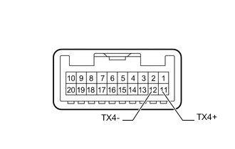
Remove the radio receiver assembly.
-
Measure the resistance according to the value(s) in the table below.
Standard Resistance Tester Connection Condition Specified Condition 11 (TX4+) - 12 (TX4-) Always 60 to 80 Ω Result Proceed to OK NG
NG
REPLACE RADIO RECEIVER ASSEMBLY Click here
OK
-
-
CHECK HARNESS AND CONNECTOR (COMBINATION METER MIRROR ECU - MULTI-DISPLAY ASSEMBLY)
-
Disconnect the J5 combination meter mirror ECU connector.
-
Disconnect the I42 multi-display assembly connector.
-
Measure the resistance according to the value(s) in the table below.
Standard Resistance Tester Connection Condition Specified Condition J5-12 (MPX1) - I42-6 (TX1+) Always Below 1 Ω J5-13 (MPX2) - I42-18 (TX1-) Always Below 1 Ω J5-12 (MPX1) or I42-6 (TX1+) - Body ground Always 10 kΩ or higher J5-13 (MPX2) or I42-18 (TX1-) - Body ground Always 10 kΩ or higher Result Proceed to OK NG
NG
REPAIR OR REPLACE HARNESS OR CONNECTOR
OK
-
-
CHECK COMBINATION METER MIRROR ECU
-
Replace the combination meter mirror ECU.
-
Clear the DTCs.
Body Electrical > Navigation System > Clear DTCs -
Recheck for DTCs and check that no DTCs are output.
Body Electrical > Navigation System > Trouble CodesOK No DTCs are output. Result Proceed to OK NG
OK
END (COMBINATION METER MIRROR ECU IS DEFECTIVE)
NG
-
-
CHECK MULTI-DISPLAY ASSEMBLY
-
Replace the multi-display assembly.
-
Clear the DTCs.
Body Electrical > Navigation System > Clear DTCs -
Recheck for DTCs and check that no DTCs are output.
Body Electrical > Navigation System > Trouble CodesOK No DTCs are output. Result Proceed to OK NG
OK
END (MULTI-DISPLAY ASSEMBLY IS DEFECTIVE)
NG
REPLACE RADIO RECEIVER ASSEMBLY Click here
-