STEERING GEAR INSPECTION

CAUTION / NOTICE / HINT
Note
-
When using a vise, place aluminum plates between the part and vise.
-
When using a vise, do not overtighten it.
PROCEDURE
-
INSPECT TIE ROD END SUB-ASSEMBLY LH
-
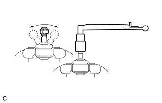
Secure the tie rod end between aluminum plates in a vise.
Note
Do not overtighten the vise.
-
Install the nut to the stud bolt.
-
Flip the ball joint back and forth 5 times.
-
Set a torque wrench on the nut, turn the ball joint continuously at a rate of 3 to 5 seconds per turn, and check the turning torque on the 5th turn.
Standard turning torque 0.98 to 3.92 N*m (10.0 to 39.9 kgf*cm, 8.68 to 34.6 in.*lbf) If the turning torque is not within the specified range, replace the tie rod end sub-assembly LH with a new one.
-
-
INSPECT TIE ROD END SUB-ASSEMBLY RH
Tech Tips
Use the same procedure described for the LH side.
-
INSPECT TOTAL PRELOAD
Note
Inspect the total preload in a no-load condition by removing the tie rod end sub-assemblies RH and LH, and steering rack boots.
-
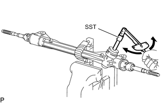
Install SST to the pinion shaft and turn it left and right 5 times or more.
- SST
- 09616-00011
-
Using a torque wrench and SST, turn the pinion shaft continuously at a rate of 4 to 6 seconds per turn to inspect the total preload of the steering gear assembly.
Total preload 0.7 to 1.25 N*m (8 to 12 kgf*cm, 7 to 11 in.*lbf) Note
Perform the inspection with the steering rack centered.
If the total preload is not within the specified range, replace the steering gear assembly with a new one.
-