STEERING HEATER SWITCH INSPECTION
PROCEDURE
-
REMOVE NO. 2 COMBINATION SWITCH ASSEMBLY
-
INSPECT NO. 2 COMBINATION SWITCH ASSEMBLY
-
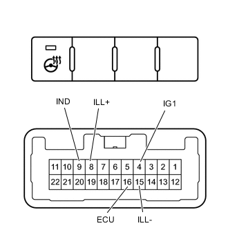
*a Component without harness connected
(No. 2 Combination Switch Assembly))
Measure the voltage according to the value (s) in the table below.
Standard Voltage Tester Connection (Positive (+) Tester Probe - Negative (-) Tester Probe) Switch Condition Specified Condition 4(IG1) - 9(IND) Always Below 1.25 V 16(ECU) - 9(IND) Steering heater switch is pushed Below 1.25 V Tech Tips
As the circuit has a diode, perform the measurement in diode test mode, and do not mistake the polarity.
-
Measure the resistance according to the value (s) in the table below
Standard Resistance Tester Connection Switch Condition Specified Condition 4(IG1) - 16(ECU) Steering heater switch is pushed Below 1 Ω Steering heater switch is not pushed 10 kΩ or higher -
Measure the voltage according to the value (s) in the table below.
-
Measure the resistance according to the value (s) in the table below.
-
Apply battery voltage between the terminals of the switch, and check the illumination condition of the No. 2 combination switch assembly (AWD lock mode switch).
Standard Measurement Condition Specified Condition Battery positive (+) → 8 (ILL+)
Battery negative (-) → 15 (ILL-)
Illuminates If the result is not as specified, replace the No. 2 combination switch assembly (Steering heater switch).
-
-
INSTALL NO. 2 COMBINATION SWITCH ASSEMBLY