HEATED STEERING WHEEL SYSTEM TERMINALS OF ECU
-
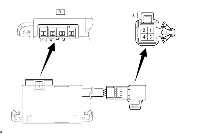
STEERING WHEEL HEATER CONTROL ASSEMBLY (w/o Steering Wheel Vibration)
Tech Tips
Perform the inspection from the harness side with the connectors connected.
-
Measure the voltage or resistance according to the value(s) in the table below.
Terminal No. (Symbol) Terminal Description Condition Specified Condition A-1 (CCU) - Body ground LED output signal Engine switch on (IG), steering heater switch on Below 3 V A-2 (CCV) - Body ground Steering heater switch input signal Engine switch on (IG), steering heater switch pressed and held 11 to 14 V A-3 (CCX) - Body ground Ground Always Below 1 Ω A-4 (CCW) - Body ground IG power supply Engine switch on (IG) 11 to 14 V B-1 (TH1) - Body ground Thermistor input signal Engine switch on (IG), steering heater switch on 1.5 to 4.5 V*1 B-2 (TH2) - Body ground Thermistor ground Engine switch on (IG), steering heater switch on Below 1 V B-3 (SH2) - Body ground Heater output signal Engine switch on (IG), steering heater switch on 11 to 14 V*2 B-4 (SH1) - Body ground Heater ground Engine switch on (IG), steering heater switch on Below 1 V Tech Tips
-
*1: When ambient temperature is 0 to 40°C (32 to 104°F).
-
*2: The current to the heater turns ON/OFF depending on the temperature of the thermistor. As a result, it may take several minutes before a voltage value is output.
-
-
-
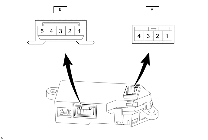
STEERING HEATER AND VIBRATION ECU (w/ Steering Wheel Vibration)
Tech Tips
Perform the inspection from the harness side with the connectors connected.
-
Measure the voltage or resistance according to the value(s) in the table below.
Terminal No. (Symbol) Terminal Description Condition Specified Condition A-4 (IG) - Body ground IG power supply Engine switch on (IG) 11 to 14 V A-3 (SW) - Body ground Steering heater switch input signal Engine switch on (IG), steering heater switch pressed and held 11 to 14 V A-2 (LED) - Body ground LED output signal Engine switch on (IG), Heated steering wheel system operating Below 3 V A-1 (GND) - Body ground Ground Always Below 1 Ω B-5 (SH1) - Body ground Heater output signal Engine switch on (IG), Heated steering wheel system operating 11 to 14 V(*1) B-3 (TH1) - Body ground Thermistor input signal Engine switch on (IG), Heated steering wheel system operating 2.5 to 4.8 V(*2) B-2 (TH2) - Body ground Thermistor ground Engine switch on (IG), Heated steering wheel system operating Below 1 V B-1 (SH2) - Body ground Heater ground Engine switch on (IG), Heated steering wheel system operating Below 1 V Tech Tips
-
*1: The current to the heater turns ON/OFF depending on the temperature of the thermistor. As a result, it may take several minutes before a voltage value is output.
-
*2: When ambient temperature is 0 to 40°C (32 to 104°F).
-
-