POWER STEERING SYSTEM(for Power Tilt and Power Telescopic Steering Column) CALIBRATION
-
TORQUE SENSOR ZERO POINT CALIBRATION (USING THE GTS)
Note
Perform torque sensor zero point calibration if any of the following conditions occur:
-
The power steering ECU assembly has been replaced.
-
The electric power steering column sub-assembly has been replaced.
-
There is a difference in steering effort between turning left and right.
-
Perform inspection before calibration.
-
Turn the engine switch off.
-
Connect the GTS to the DLC3.
-
Turn the engine switch on (IG).
-
Turn the GTS on.
-
Enter the following menus: Chassis / EMPS / Data List.
-
Check the values by referring to the table below.
Chassis > EMPS > Data ListTester Display Measurement Item Range Normal Condition Diagnostic Note IG Power Supply IG power source voltage Min.: 0.0000 V
Max.: 20.1531 V
w/o Stop and Start System:
Engine switch on (IG): 8 to 16 V
w/ Stop and Start System:
Engine switch on (IG): 10.5 to 16 V
-
Chassis > EMPS > Data ListTester Display IG Power Supply Note
If the IG power supply voltage is 8 V or less, calibration cannot be performed. In this case, charge or replace the battery, and then perform calibration.
-
-
Perform torque sensor zero point calibration.
-
Set the steering wheel to the center point and align the front wheels straight ahead.
-
Turn the engine switch off.
-
Connect the GTS to the DLC3.
-
Turn the engine switch on (IG).
-
Turn the GTS on.
-
Enter the following menus: Chassis / EMPS / Utility / Torque Sensor Adjustment.
Chassis > EMPS > UtilityTester Display Torque Sensor Adjustment Note
-
Do not turn the steering wheel sharply.
-
Do not touch the steering wheel during torque sensor zero point calibration.
-
-
Check for DTCs.
Chassis > EMPS > Trouble CodesNote
If DTC C1515/15, C1516/16 or C1534/25 is output, perform troubleshooting for the corresponding DTC.
-
-
-
TORQUE SENSOR ZERO POINT CALIBRATION (USING SST CHECK WIRE)
Note
Perform torque sensor zero point calibration if any of the following conditions occur:
-
The power steering ECU assembly has been replaced.
-
The electric power steering column sub-assembly has been replaced.
-
There is a difference in steering effort between turning left and right.
-
Perform inspection before calibration.
-
Turn the engine switch off.
-
Disconnect the n2 power steering ECU assembly connector.
-
Turn the engine switch on (IG).
-
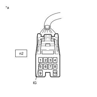
*a Front view of wire harness connector
(to Power Steering ECU Assembly)
Measure the voltage according to the value(s) in the table below.
Note
If the IG power supply voltage is 8 V or less, calibration cannot be performed. In this case, charge or replace the battery, and then perform calibration.
-
Turn the engine switch off.
-
Reconnect the n2 power steering ECU assembly connector.
-
-
Clear sensor calibration value.
-
Turn the engine switch off.
-
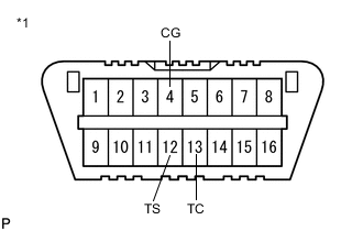
*1 DLC3 Using SST, connect terminals 12 (TS) and 4 (CG) of the DLC3.
- SST
- 09843-18040
Note
Connect the terminals correctly to avoid a malfunction.
-
Turn the engine switch on (IG) and then connect and disconnect terminals 13 (TC) and 4 (CG) at least 20 times in 20 seconds.
-
Check that the power steering warning light (red) blinks and then remains illuminated.
Tech Tips
The power steering warning light (red) illumination indicates that DTC C1515/15 has been stored.
-
Turn the engine switch off.
Note
After erasing the sensor calibration value, zero point calibration cannot be performed if the engine switch is on (IG).
-
-
Perform torque sensor zero point calibration.
-
Set the steering wheel to the center point and align the front tires straight ahead.
-
Turn the engine switch off.
-
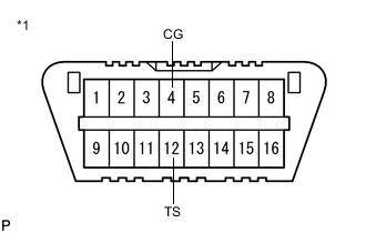
*1 DLC3 Using SST, connect terminals 12 (TS) and 4 (CG) of the DLC3.
- SST
- 09843-18040
Note
Connect the terminals correctly to avoid a malfunction.
-
Turn the engine switch on (IG).
Note
-
Do not touch the steering wheel for 3 seconds before and after entering test mode.
-
The power steering warning light (red) illuminates, but this is not a malfunction.
Tech Tips
-
Torque sensor zero point calibration is performed as a result of entering test mode.
-
When entering test mode, the power steering warning light (red) illuminates for 2 seconds, and then the power steering warning light (yellow) illuminates for 2 seconds. Afterward, the power steering warning light (red) illuminates again. When torque sensor zero point calibration ends normally, the power steering warning light (red) blinks at 0.125 second (4 Hz) intervals.
-
-
Check the power steering warning light (red) for blinking which indicates that torque sensor zero point calibration has ended normally, and then disconnect the 12 (TS) - 4 (CG) terminals of the DLC3 (test mode completed).
-
Check for DTCs.
Note
If DTC C1515/15, C1516/16 or C1534/25 is output, perform troubleshooting for the corresponding DTC.
-
-
-
ASSIST MAP WRITING (USING THE GTS)
Note
Perform assist map writing if the following condition occurs:
The power steering ECU assembly has been replaced.
-
Turn the engine switch off.
-
Connect the GTS to the DLC3.
-
Turn the engine switch on (IG).
-
Turn the GTS on.
-
Enter the following menus: Chassis / EMPS / Utility / Signal Check.
Chassis > EMPS > UtilityTester Display Signal Check Tech Tips
-
Follow the instructions on the GTS to perform Signal Check.
-
With DTC C1581/26 output, performing Signal Check will cause the power steering ECU assembly to enter Test Mode and the assist map will be written automatically.
-
-
Wait for 5 seconds or more.
-
Check for DTCs.
Chassis > EMPS > Trouble CodesTech Tips
After writing the assist map, if DTC C1581/26 is output, perform the troubleshooting procedure for DTC C1581/26.
-
-
ASSIST MAP WRITING (USING SST CHECK WIRE)
Note
Perform assist map writing if the following condition occurs:
The power steering ECU assembly has been replaced.
-
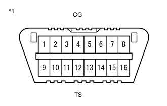
*1 DLC3 Turn the engine switch off.
-
Using SST, connect terminals 12 (TS) and 4 (CG) of the DLC3.
- SST
- 09843-18040
Note
Connect the terminals correctly to avoid a malfunction.
-
Turn the engine switch on (IG).
-
Wait for 5 seconds or more.
-
Check for DTCs.
Tech Tips
After writing the assist map, if DTC C1581/26 is output, perform the troubleshooting procedure for DTC C1581/26.
-