ELECTRIC PARKING BRAKE SYSTEM, Diagnostic DTC:C13A3/31, C13AB/33
| DTC Code | DTC Name |
|---|---|
| C13A3/31 | Open or Short in Lock Switch Circuit |
| C13AB/33 | Lock Switch Circuit |
DESCRIPTION
When the electric parking brake switch (integration control and panel assembly) is pulled to the lock side, a lock request signal is output to the parking brake ECU assembly.
| DTC No. | Detection Item | DTC Detection Condition | Trouble Area | Memory | Note |
|---|---|---|---|---|---|
| C13A3/31 | Open or Short in Lock Switch Circuit | All of following conditions are met:
Tech Tips *: When battery voltage is 12 V |
|
Yes | An electric parking brake system malfunction is displayed on the multi-information display. |
| C13AB/33 | Lock Switch Circuit | Both of following conditions are met:
|
|
Yes | An electric parking brake system malfunction is displayed on the multi-information display. |
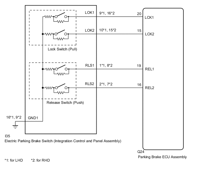
WIRING DIAGRAM
CAUTION / NOTICE / HINT
Note
-
Before disconnecting connectors or fuses, turn the engine switch off and wait 20 seconds or more.
-
When the electric parking brake switch (integration control and panel assembly) is pulled and held for 1 second or more without being pulled fully to the lock side, one of the 2 linked contacts may turn on while the other one turns off causing this DTC to be stored (system is not malfunctioning).
-
When replacing the parking brake ECU assembly, operate the electric parking brake switch (integration control and panel assembly), as the parking brake indicator light (red) blinks when the engine switch is first turned on (IG).
PROCEDURE
-
INSPECT ELECTRIC PARKING BRAKE SWITCH (INTEGRATION CONTROL AND PANEL ASSEMBLY)
-
Remove the electric parking brake switch (integration control and panel assembly).
-
Inspect the electric parking brake switch (integration control and panel assembly).
Result Proceed to OK NG
NG 
REPLACE INTEGRATION CONTROL AND PANEL ASSEMBLY Click here
OK 
-
-
CHECK HARNESS AND CONNECTOR (PARKING BRAKE ECU ASSEMBLY - ELECTRIC PARKING BRAKE SWITCH (INTEGRATION CONTROL AND PANEL ASSEMBLY))
-
Disconnect the I35 electric parking brake switch (integration control and panel assembly) connector.
-
Disconnect the Q24 parking brake ECU assembly connector.
-
Measure the resistance according to the value(s) in the table below.
Standard Resistance for LHD: Tester Connection Condition Specified Condition Q24-20 (LCK1) - I35-9 (LOK1) Always Below 5 Ω Q24-15 (LCK2) - I35-10 (LOK2) Always Below 5 Ω Q24-20 (LCK1) or I35-9 (LOK1) - Body ground Always 10 kΩ or higher Q24-15 (LCK2) or I35-10 (LOK2) - Body ground Always 10 kΩ or higher I35-16 (GND1) - Body ground Always Below 5 Ω for RHD: Tester Connection Condition Specified Condition Q24-20 (LCK1) - I35-16 (LOK1) Always Below 5 Ω Q24-15 (LCK2) - I35-15 (LOK2) Always Below 5 Ω Q24-20 (LCK1) or I35-16 (LOK1) - Body ground Always 10 kΩ or higher Q24-15 (LCK2) or I35-15 (LOK2) - Body ground Always 10 kΩ or higher I35-9 (GND1) - Body ground Always Below 5 Ω Result Proceed to OK NG
NG
REPAIR OR REPLACE HARNESS OR CONNECTOR
OK
-
-
CHECK DTC
-
Clear the DTCs.
Chassis > Electric Parking Brake > Clear DTCs -
Turn the engine switch off.
-
Turn the engine switch on (IG).
-
Perform a lock operation with the electric parking brake switch (integration control and panel assembly).
Tech Tips
When the electric parking brake switch (integration control and panel assembly) is pulled and held for 1 second or more without being pulled fully to the lock side, one of the 2 linked contacts may turn on while the other one turns off causing this DTC to be stored (system is not malfunctioning).
-
Check for DTCs.
Chassis > Electric Parking Brake > Trouble CodesResult Proceed to DTC is output DTC is not output
DTC is output
REPLACE PARKING BRAKE ECU ASSEMBLY Click here
DTC is not output
USE SIMULATION METHOD TO CHECK Click here
-