ELECTRIC PARKING BRAKE SYSTEM TERMINALS OF ECU
-
CHECK PARKING BRAKE ECU ASSEMBLY
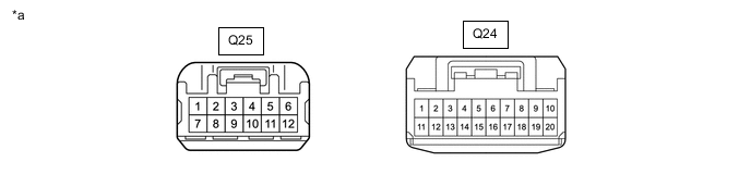
*a Front view of wire harness connector
(to Parking Brake ECU Assembly)
- -
-
Disconnect the parking brake ECU assembly connectors.
-
Measure the voltage and resistance according to the values in the table below.
Terminal No. (Symbol) Wiring Color Terminal Description Condition Specified Condition Q25-7 (+B) - Body ground B Parking brake motor RH (Parking brake actuator assembly RH) power supply Always 11 to 14 V Q25-9 (GND1) - Body ground W-B Ground Always Below 1 Ω Q25-12 (+B2) - Body ground W Parking brake motor LH (Parking brake actuator assembly LH) power supply Always 11 to 14 V Q24-3 (BECU) - Body ground B Parking brake ECU assembly power supply Always 11 to 14 V Q24-5 (IG) - Body ground V IG power supply Engine switch on (IG) 11 to 14 V -
Connect the parking brake ECU assembly connectors.
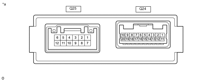
*a Component with harness connected
(Parking Brake ECU Assembly)
- - -
Measure the voltage according to the values in the table below.
Terminal No. (Symbol) Wiring Color Terminal Description Condition Specified Condition Q25-1 (MRR+) - Body ground B Parking brake motor RH (Parking brake actuator assembly RH) (+)
-
Engine switch on (IG)
-
Parking brake not operating
3.9 to 6.2 V Q25-3 (MRR-) - Body ground W Parking brake motor RH (Parking brake actuator assembly RH) (-)
-
Engine switch on (IG)
-
Parking brake not operating
3.9 to 6.2 V Q25-4 (MRL+) - Body ground L Parking brake motor LH (Parking brake actuator assembly LH) (+)
-
Engine switch on (IG)
-
Parking brake not operating
3.9 to 6.2 V Q25-6 (MRL-) - Body ground R Parking brake motor LH (Parking brake actuator assembly LH) (-)
-
Engine switch on (IG)
-
Parking brake not operating
3.9 to 6.2 V Q24-4 (TX) - Body ground R Combination meter assembly communication signal 20 seconds after engine switch turned off 9 to 14 V Q24-13 (LPA) - Body ground G AUTO indicator light
-
Engine switch on (IG)
-
AUTO indicator light off
9 to 14 V Q24-14 (POL) - Body ground P Electric parking brake switch indicator light
-
Engine switch on (IG)
-
Electric parking brake switch indicator light off
9 to 14 V Q24-15 (LCK2) - Body ground W Electric parking brake switch (Integration control and panel assembly) lock 2
-
Engine switch on (IG)
-
Electric parking brake switch (Integration control and panel assembly) off (released)
6.5 to 10 V
-
Engine switch on (IG)
-
Electric parking brake switch (Integration control and panel assembly) pulled and held to lock side
2.8 to 5 V Q24-16 (REL2) - Body ground R Electric parking brake switch (Integration control and panel assembly) release 2
-
Engine switch on (IG)
-
Electric parking brake switch (Integration control and panel assembly) off (released)
6.5 to 10 V
-
Engine switch on (IG)
-
Electric parking brake switch (Integration control and panel assembly) pushed and held to release side
2.8 to 5 V Q24-19 (REL1) - Body ground L Electric parking brake switch (Integration control and panel assembly) release 1
-
Engine switch on (IG)
-
Electric parking brake switch (Integration control and panel assembly) off (released)
6.5 to 10 V
-
Engine switch on (IG)
-
Electric parking brake switch (Integration control and panel assembly) pushed and held to release side
2.8 to 5 V Q24-20 (LCK1) - Body ground B Electric parking brake switch (Integration control and panel assembly) lock 1
-
Engine switch on (IG)
-
Electric parking brake switch (Integration control and panel assembly) off (released)
1.8 to 3.3 V
-
Engine switch on (IG)
-
Electric parking brake switch (Integration control and panel assembly) pulled and held to lock side
2.2 to 3.7 V -
-