ELECTRIC PARKING BRAKE SYSTEM TEST MODE PROCEDURE
-
REAR BRAKE PAD REPLACEMENT MODE
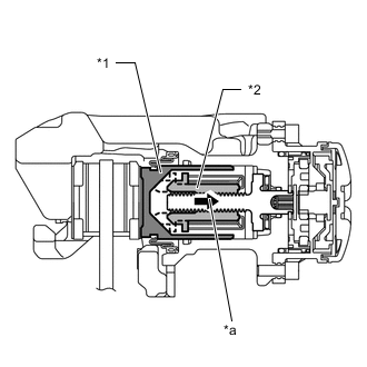
*1 Rear Disc Brake Piston *2 Nut *a Move nut back inside using pad replacement mode Tech Tips
When replacing the rear disc brake pad and rear disc, since the nut inside the rear disc brake cylinder assembly is in an advanced position, it is necessary to move the nut back inside the cylinder. The nut can be moved back using pad replacement mode.
-
Pad replacement mode
-
Turn the engine switch off.
-
Connect the GTS to the DLC3.
-
Turn the engine switch on (IG) and the GTS on.
-
Enter the following menus: Chassis / Electric Parking Brake / Utility / Check Mode.
-
Follow the GTS display and select "Next".
-
Depress the brake pedal, and then push and hold the electric parking brake switch (integration control and panel assembly) to the release side for 5 seconds or more.
Note
-
Perform this procedure with the engine switch on (IG).
-
Hold the brake pedal until the system changes to pad replacement mode. If the brake pedal is not depressed, the cylinder boot may become twisted.
-
When the system changes to pad replacement mode, DTC C13A7/43 may be stored. If the DTC is stored, clear the DTCs after the procedure (rear brake pad replacement, etc.) is complete.
Tech Tips
When entering pad replacement mode, the parking brake indicator light (red) flashes (0.25 second intervals). After a short time passes, the parking brake actuator assembly operates (if operated from the parking brake locked condition, the motor of the parking brake actuator assembly is temporarily stopped after being operated and then operation starts again), and once the assembly finishes operating, the parking brake indicator light (red) flashes slowly (1 second intervals) (nut moves back inside the cylinder and system enters pad replacement mode).
-
When Using the GTS:
Chassis > Electric Parking Brake > UtilityTester Display Check Mode
-
Turn the engine switch off.
-
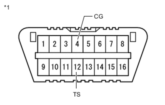
*1 DLC3 Using SST, connect terminals 12 (TS) and 4 (CG) of the DLC3.
SST 09843-18040 Note
Do not connect the wrong terminals, as this will cause parts to be damaged.
-
Turn the engine switch on (IG).
-
Within 8 seconds, operate the electric parking brake switch (integration control and panel assembly) to perform 3 on operations on the lock side (off (release) to on (pull)) and 3 on operations on the release side (off (release) to on (push)).
Note
If the operation is performed too quickly, the system may not respond. If the system does not respond, perform the operation again at a slower speed.
Tech Tips
The parking brake indicator light (red) flashes (0.25 second intervals).
-
Depress the brake pedal, and then push and hold the electric parking brake switch (integration control and panel assembly) to the release side for 5 seconds or more.
Note
-
Perform this procedure with the engine switch on (IG).
-
Hold the brake pedal until the system changes to pad replacement mode. If the brake pedal is not depressed, the cylinder boot may become twisted.
-
When the system changes to pad replacement mode, DTC C13A7/43 may be stored. If the DTC is stored, clear the DTCs after the procedure (rear brake pad replacement, etc.) is complete.
Tech Tips
After a short time passes, the parking brake actuator assembly operates (if operated from the parking brake locked condition, the motor of the parking brake actuator assembly is temporarily stopped after being operated and then operation starts again), and once the assembly finishes operating, the parking brake indicator light (red) flashes slowly (1 second intervals) (nut moves back inside the cylinder and system enters pad replacement mode).
-
When not Using the GTS:
-
-
Turn the engine switch off.
Note
Do not operate the electric parking brake switch (integration control and panel assembly) until the procedures are complete. If operated, the system will return to its normal condition.
-
Disconnect the GTS from the DLC3.
When Using the GTS:
-
Disconnect SST from the DLC3.
When not Using the GTS:
-
-
Normal condition recovery
-
After the procedure (rear brake pad replacement, etc.) is complete, perform an electric parking brake switch (integration control and panel assembly) lock operation.
Note
-
When performing work (replacing the rear brake pad, etc.), do not operate the electric parking brake switch (integration control and panel assembly) or turn the engine switch on (IG) and operate the shift lever. If the electric parking brake switch (integration control and panel assembly) or shift lever is operated, the parking brake may operate and the rear disc brake piston may fall off. Also, make sure to disconnect the connector of the parking brake actuator assembly or disconnect the cable from the negative (-) battery terminal.
-
When DTC C13A7/43 is stored, clear the DTCs.
-
-
-