REAR BRAKE INSTALLATION
CAUTION / NOTICE / HINT
Tech Tips
-
Use the same procedure for the RH and LH sides.
-
The following procedure is for the LH side.
PROCEDURE
-
INSTALL REAR DISC
-
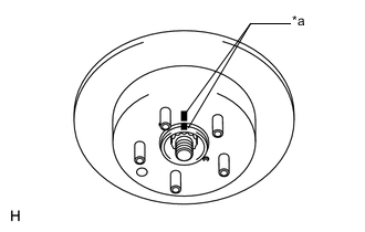
*a Matchmarks Align the matchmarks of the rear disc and axle hub and install the rear disc.
Tech Tips
When replacing the disc with a new one, select the installation position where the rear disc has the smallest runout.
-
-
INSTALL REAR DISC BRAKE BUSH DUST BOOT
-
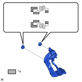
*a Lithium soap base glycol grease Apply a light coat of lithium soap base glycol grease to the entire circumference of a new rear disc brake bush dust boot where it contacts the rear disc brake cylinder mounting LH, and the entire inner circumference of both of its ends.
Tech Tips
Apply at least 0.3 g (0.01 oz.) of lithium soap base glycol grease to the rear disc brake bush dust boot.
-
Install the 2 rear disc brake bush dust boots to the rear disc brake cylinder mounting LH.
-
-
INSTALL REAR DISC BRAKE CYLINDER SLIDE BUSH
-
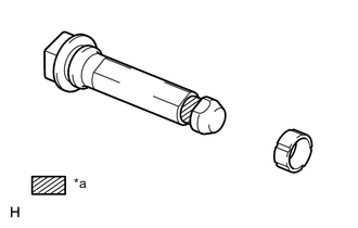
*a Lithium soap base glycol grease Apply a light coat of lithium soap base glycol grease to a new rear disc brake rear cylinder slide pin where it contacts the rear disc brake cylinder slide bush.
-
Install the rear disc brake cylinder slide bush to the rear disc brake rear cylinder slide pin.
-
-
INSTALL REAR DISC BRAKE CYLINDER SLIDE PIN
-
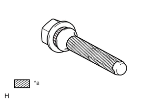
*a Lithium soap base glycol grease Apply a light coat of lithium soap base glycol grease to the sliding part of the rear disc brake cylinder slide pin.
-
Install the rear disc brake cylinder slide pin to the rear disc brake cylinder mounting LH.
-
Push the rear disc brake cylinder slide pin into the rear disc brake bush dust boot to align them.
-
-
INSTALL REAR DISC BRAKE REAR CYLINDER SLIDE PIN
-
*a Lithium soap base glycol grease Apply a light coat of lithium soap base glycol grease to the sliding part and the seal surface of the rear disc brake rear cylinder slide pin.
-
Install the rear disc brake rear cylinder slide pin to the disc brake cylinder mounting LH.
-
Push the rear disc brake rear cylinder slide pin into the rear disc brake bush dust boot to align them.
-
-
INSTALL DISC BRAKE CYLINDER MOUNTING LH
-
Install the disc brake cylinder mounting LH with the 2 bolts.
- Torque:
- 104 N*m { 1061 kgf*cm, 77 ft.*lbf }
-
-
INSTALL REAR DISC BRAKE PAD SUPPORT PLATE
-
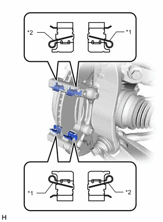
*1 Rear No. 1 Disc Brake Pad Support Plate *2 Rear No. 2 Disc Brake Pad Support Plate Install the 4 pad support plates to the disc brake cylinder mounting LH as shown in the illustrtion.
Note
-
The shapes of the rear disc brake pad support plates differ. Therefore, when replacing a rear disc brake pad support plate with a new plate, make sure to check the part number and shape prior to installation.
-
When reusing a rear disc brake pad support plate, make sure to check the installation position using the matchmark placed during removal proper to installation.
-
-
-
INSTALL REAR ANTI-SQUEAL SHIM KIT
-
for Type A:
-

Disc brake grease Apply disc brake grease to both sides of the 2 rear No. 1 disc brake anti-squeal shims as shown in the illustration.
Note
Make sure that disc brake grease is not applied onto the lining surface.
-
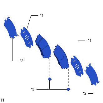
*1 Rear No. 1 Disc Brake Anti-squeal Shim *2 Rear No. 2 Disc Brake Anti-squeal Shim *3 Pad Wear Indicator Plate Install the 2 rear No. 1 disc brake anti-squeal shims and 2 rear No. 2 disc brake anti-squeal shims to the rear disc brake pads.
Note
-
When replacing a worn pad, the shims must be replaced together with the pads.
-
Install the shims in the correct positions and direction as shown in the illustration.
-
-
-
for Type B:
-
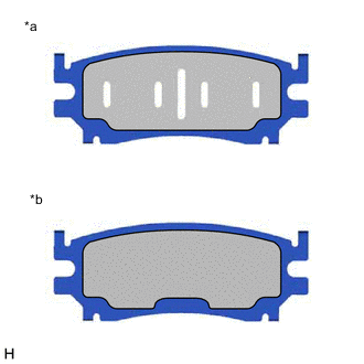
*a Inner Side *b Outer Side Disc brake grease Apply disc brake grease to both surfaces of the inner rear No. 1 disc brake anti-squeal shim and only to the inner surface of the outer rear disc brake anti-squeal shim.
Note
Make sure that disc brake grease is not applied onto the lining surface.
-
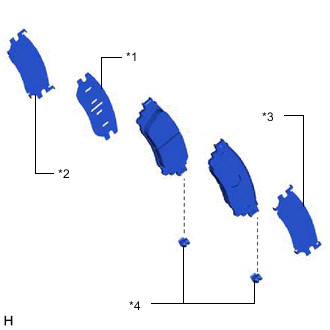
*1 Rear No. 1 Disc Brake Anti-squeal Shim *2 Rear No. 2 Disc Brake Anti-squeal Shim *3 Rear Disc Brake Anti-squeal Shim *4 Pad Wear Indicator Plate Install the rear No. 1 disc brake anti-squeal shim and rear No. 2 disc brake anti-squeal shim to the inner rear disc brake pad.
Note
-
When replacing a worn pad, the shims must be replaced together with the pads.
-
Install the shims in the correct positions and direction as shown in the illustration.
-
-
Install the rear disc brake anti-squeal shim to the outer rear disc brake pad.
Note
When replacing a worn pad, the shims must be replaced together with the pads.
-
-
-
INSTALL REAR DISC BRAKE PAD
-
Install the 2 new pad wear indicator plates to the rear disc brake pads.
Note
Install the pad wear indicator plates in the correct positions and directions.
-
Install the 2 rear disc brake pads to the disc brake cylinder mounting LH.
Note
Make sure there is no oil or grease on the friction surface of the rear disc brake pads and rear disc.
Tech Tips
If the rear disc brake pad has an identification mark, be sure to confirm the installation location.
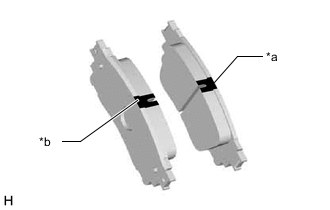
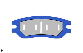
*a Inner Side (Purple) *b Outer Side (White)
-
-
INSTALL REAR DISC BRAKE CYLINDER ASSEMBLY LH
-
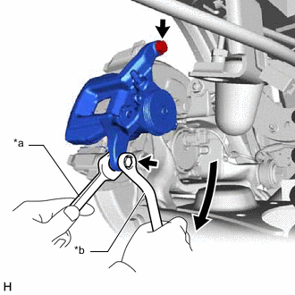
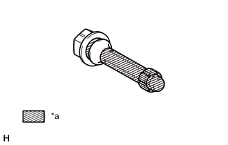
*a Hold *b Turn Hold the rear disc brake cylinder slide pins and install the rear disc brake cylinder assembly LH to the disc brake cylinder mounting LH with the 2 new bolts.
- Torque:
- 34.3 N*m { 350 kgf*cm, 25 ft.*lbf }
-
-
INSTALL PARKING BRAKE ACTUATOR ASSEMBLY LH
-
Apply a light coat of lithium soap base glycol grease to the new O-ring.
-
Install the O-ring to the rear disc brake cylinder assembly LH.
-
Using a 5 mm hexagon socket wrench, install the parking brake actuator assembly LH with the 2 bolts.
- Torque:
- 8.4 N*m { 86 kgf*cm, 74 in.*lbf }
-
Connect the connector to the parking brake actuator assembly.
-
-
CONNECT REAR FLEXIBLE HOSE LH
-
Install a new gasket and connect the rear flexible hose LH with a new union bolt.
- Torque:
- 30.4 N*m { 310 kgf*cm, 22 ft.*lbf }
Tech Tips
Install the flexible hose lock securely in the lock hole in the rear disc brake cylinder assembly LH.
-
-
BLEED BRAKE LINE
-
INSTALL REAR WHEEL
-
RECOVERY TO NORMAL
-
After performing repairs, operate the integration control and panel assembly (electric parking brake switch).
-