TIRE PRESSURE WARNING SYSTEM, Diagnostic DTC:B1247

| DTC Code | DTC Name |
|---|---|
| B1247 | Tire Pressure Monitor Receiver Communication Stop |
DESCRIPTION
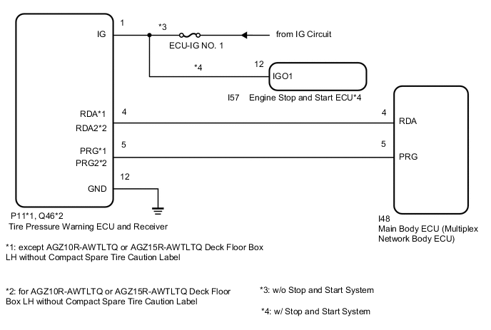
The main body ECU (multiplex network body ECU) and tire pressure warning ECU and receiver are connected using 2 direct lines that they use to communicate with each other.
| DTC No. | Detection Item | DTC Detection Condition | Trouble Area | Note |
|---|---|---|---|---|
| B1247 | Tire Pressure Monitor Receiver Communication Stop | In diagnostic mode, an applicable RDA signal cannot be received within 10 seconds after a PRG signal is sent from the main body ECU (multiplex network body ECU). |
|
This DTC for main body ECU (multiplex network body ECU) |
-
*1: w/o Stop and Start System
-
*2: w/ Stop and Start System
WIRING DIAGRAM
CAUTION / NOTICE / HINT
Note
-
When replacing the tire pressure warning ECU and receiver, read the transmitter IDs stored in the old ECU using the GTS and write them down before removal.
-
It is necessary to perform initialization after registration Click here of the transmitter IDs into the tire pressure warning ECU and receiver after the ECU has been replaced.
-
If the main body ECU (multiplex network body ECU) is replaced, refer to the Service Bulletin.
-
As the door control battery is installed between the vehicle battery and main body ECU (multiplex network body ECU), first perform the inspections in On-Vehicle Inspection to confirm that there are no malfunctions in the power source circuit for the main body ECU (multiplex network body ECU) before performing this troubleshooting procedure.*
*: w/ Rear Pretensioner
Tech Tips
w/o Stop and Start System:
Inspect the fuses for circuits related to this system before performing the following inspection procedure.
PROCEDURE
-
CHECK HARNESS AND CONNECTOR (MAIN BODY ECU (MULTIPLEX NETWORK BODY ECU) - TIRE PRESSURE WARNING ECU AND RECEIVER)
-
Disconnect the P11*1 or Q46*2 tire pressure warning ECU and receiver connector.
-
*1: except AGZ10R-AWTLTQ or AGZ15R-AWTLTQ Deck Floor Box LH without Compact Spare Tire Caution Label
-
*2: for AGZ10R-AWTLTQ or AGZ15R-AWTLTQ Deck Floor Box LH without Compact Spare Tire Caution Label
-
-
Disconnect the I48 main body ECU (multiplex network body ECU) connector.
-
Measure the resistance according to the value(s) in the table below.
Standard Resistance except AGZ10R-AWTLTQ or AGZ15R-AWTLTQ Deck Floor Box LH without Compact Spare Tire Caution Label Tester Connection Condition Specified Condition P11-4 (RDA) - I48-4 (RDA) Always Below 1 Ω P11-4 (RDA) or I48-4 (RDA) - Body ground Always 10 kΩ or higher for AGZ10R-AWTLTQ or AGZ15R-AWTLTQ Deck Floor Box LH without Compact Spare Tire Caution Label Tester Connection Condition Specified Condition Q46-4 (RDA2) - I48-4 (RDA) Always Below 1 Ω Q46-4 (RDA2) or I48-4 (RDA) - Body ground Always 10 kΩ or higher Result Proceed to OK NG
NG 
REPAIR OR REPLACE HARNESS OR CONNECTOR
OK 
-
-
CHECK HARNESS AND CONNECTOR (POWER SOURCE OF TIRE PRESSURE WARNING ECU AND RECEIVER)
-
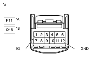
*A except AGZ10R-AWTLTQ or AGZ15R-AWTLTQ Deck Floor Box LH without Compact Spare Tire Caution Label *B for AGZ10R-AWTLTQ or AGZ15R-AWTLTQ Deck Floor Box LH without Compact Spare Tire Caution Label *a Front view of wire harness connector
(to Tire Pressure Warning ECU and Receiver)
Measure the resistance according to the value(s) in the table below.
Standard Resistance except AGZ10R-AWTLTQ or AGZ15R-AWTLTQ Deck Floor Box LH without Compact Spare Tire Caution Label Tester Connection Condition Specified Condition P11-12 (GND) - Body ground Always Below 1 Ω for AGZ10R-AWTLTQ or AGZ15R-AWTLTQ Deck Floor Box LH without Compact Spare Tire Caution Label Tester Connection Condition Specified Condition Q46-12 (GND) - Body ground Always Below 1 Ω -
Measure the voltage according to the value(s) in the table below.
Standard Voltage except AGZ10R-AWTLTQ or AGZ15R-AWTLTQ Deck Floor Box LH without Compact Spare Tire Caution Label Tester Connection Condition Specified Condition P11-1 (IG) - Body ground Engine switch on (IG) 10 to 16 V for AGZ10R-AWTLTQ or AGZ15R-AWTLTQ Deck Floor Box LH without Compact Spare Tire Caution Label Tester Connection Condition Specified Condition Q46-1 (IG) - Body ground Engine switch on (IG) 10 to 16 V Result Proceed to OK NG (w/o Stop and Start System) NG (w/ Stop and Start System)
NG (w/o Stop and Start System)
REPAIR OR REPLACE HARNESS OR CONNECTOR
NG (w/ Stop and Start System)
INSPECT STOP AND START SYSTEM (BACKUP BOOST CONVERTER CIRCUIT) Click here
OK
-
-
REPLACE TIRE PRESSURE WARNING ECU AND RECEIVER
-
Replace the tire pressure warning ECU and receiver.
except AGZ10R-AWTLTQ or AGZ15R-AWTLTQ Deck Floor Box LH without Compact Spare Tire Caution Label: Click here
for AGZ10R-AWTLTQ or AGZ15R-AWTLTQ Deck Floor Box LH without Compact Spare Tire Caution Label: Click here
Result Proceed to NEXT
NEXT
-
-
CHECK DTC OUTPUT
-
Clear the DTCs.
Body Electrical > Main Body > Clear DTCs -
Turn the engine switch off.
-
Turn the engine switch on (IG).
-
Check for DTCs.
Body Electrical > Main Body > Trouble CodesOK DTC B1247 is not output. Result Proceed to OK NG
OK
END
NG
REPLACE MAIN BODY ECU (MULTIPLEX NETWORK BODY ECU) for LHD: Click here
REPLACE MAIN BODY ECU (MULTIPLEX NETWORK BODY ECU) for RHD: Click here -