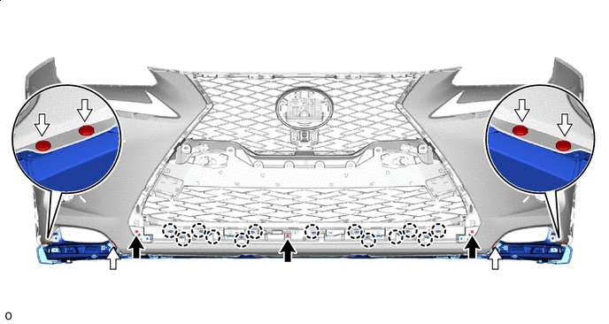
FRONT BUMPER(for Sport Package) REASSEMBLY
PROCEDURE
-
INSTALL NO. 2 MOULDING TAPE
Tech Tips
-
When installing the No. 2 moulding tape, heat the front bumper cover and No. 2 moulding tape using a heat light.
-
Use the same procedure described for the other side.
Standard Item Temperature Front Bumper Cover 20 to 30°C (68 to 86°F) No. 2 Moulding Tape 20 to 30°C (68 to 86°F) Note
Do not heat the front bumper cover and No. 2 moulding tape excessively.
-
Clean the front bumper cover surface.
-
Using a heat light, heat the front bumper cover surface.
-
Remove the double-sided tape from the front bumper cover.
-
Wipe off any tape adhesive residue with cleaner.
-
-
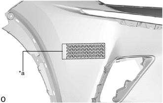
*a Scribed Line Install a new No. 2 moulding tape.
-
Using a heat light, heat the front bumper cover and No. 2 moulding tape.
-
Remove the peeling paper from the face of the No. 2 moulding tape.
Tech Tips
After removing the peeling paper, keep the exposed adhesive free from foreign matter.
-
Align the No. 2 moulding tape with the scribed line on the front bumper cover and install it as shown in the illustration.
Tech Tips
Press the No. 2 moulding tape firmly to install it.
-
-
-
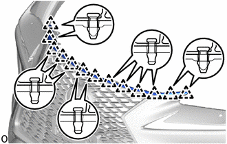
INSTALL LOWER RADIATOR GRILLE MOULDING
-
INSTALL FRONT BUMPER GUARD
-
Attach the 8 claws and install the front bumper guard to the lower radiator grille moulding.
-
-
INSTALL FRONT BUMPER NO. 2 GUARD PAD LH
-
Attach the claw to install the front bumper No. 2 guard pad LH to the lower radiator grille moulding.
-
Install the retainer.
-
-
INSTALL FRONT BUMPER NO. 2 GUARD PAD RH
Tech Tips
Use the same procedure described for the LH side.
-
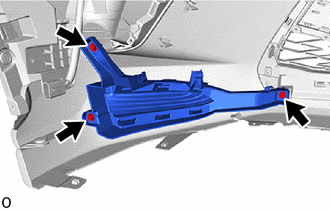
INSTALL FRONT BUMPER NO. 2 GUARD
-
Attach the 20 claws and 2 guides to install the front bumper No. 2 guard.
-
Install the 4 screws.
-
-
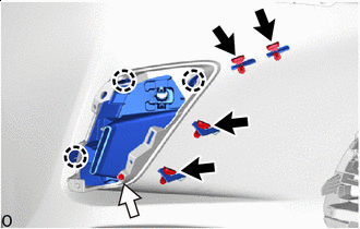
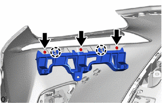
INSTALL FRONT BUMPER GUARD ASSEMBLY
-
Attach the 13 claws and install the front bumper guard assembly.
-
Install the 6 clips and 3 screws.

Screw 
Clip
-
-
INSTALL RADIATOR GRILLE ASSEMBLY
-
INSTALL HOOD TO FRONT END PANEL SEAL
-
Attach the 13 clips to install the hood to front end panel seal.
-
-
INSTALL AIR INTAKE DUCT LH
-
Attach the 2 guides to install the air intake duct LH.
-
Install the 2 clips.
-
-
INSTALL AIR INTAKE DUCT RH
Tech Tips
Use the same procedure described for the LH side.
-
INSTALL NO. 2 RADIATOR GRILLE GARNISH
-
Outside Moulding Retainer Screw Attach the 3 claws to install the No. 2 radiator grille garnish.
-
Install the screw.
-
Install the 4 outside moulding retainers.
-
-
INSTALL RADIATOR GRILLE GARNISH
Tech Tips
Use the same procedure described for the No. 2 radiator grille garnish.
-
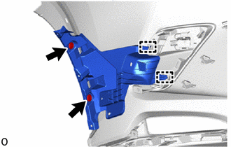
INSTALL FRONT BUMPER NO. 2 RETAINER BRACKET
-
Attach the 2 claws to install the front bumper No. 2 retainer bracket.
-
Install the 3 screws.
-
-
INSTALL FRONT BUMPER NO. 1 RETAINER BRACKET
Tech Tips
Use the same procedure described for the front bumper No. 2 retainer bracket.
-
INSTALL FOG LIGHT ASSEMBLY LH (w/ Fog Light)
-
INSTALL FOG LIGHT ASSEMBLY RH (w/ Fog Light)
Tech Tips
Use the same procedure described for the LH side.
-
INSTALL FRONT BUMPER GUARD COVER LH (w/o Fog Light)
-
Install the front bumper guard cover LH with the 3 screws.
-
-
INSTALL FRONT BUMPER GUARD COVER RH (w/o Fog Light)
Tech Tips
Use the same procedure described for the LH side.
-
INSTALL CLEARANCE LIGHT ASSEMBLY LH
-
for LED Type Turn Signal Light:
-
for Bulb Type Turn Signal Light:
-
-
INSTALL CLEARANCE LIGHT ASSEMBLY RH
Tech Tips
Use the same procedure described for the LH side.
-
INSTALL FRONT CORNER ULTRASONIC SENSOR (w/ LEXUS Parking Assist-sensor System)
-
INSTALL FRONT CENTER ULTRASONIC SENSOR (w/ LEXUS Parking Assist-sensor System)
-
INSTALL NO. 3 ENGINE ROOM WIRE
-
w/ Dynamic Radar Cruise Control System:
Connect the connector.
-
w/ LEXUS Parking Assist-sensor System:
Connect the 4 connectors.
-
w/ Panoramic View Monitor System:
Connect the connector.
-
w/o LEXUS Parking Assist-sensor System:
Attach the 7 clamps and install the No. 3 engine room wire.
-
Attach the 16 clamps to install the No. 3 engine room wire.
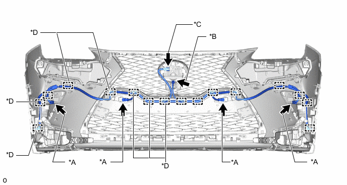
*A w/ LEXUS Parking Assist-sensor System *B w/ Panoramic View Monitor System *C w/ Dynamic Radar Cruise Control System *D w/o LEXUS Parking Assist-sensor System
-
-
INSTALL NO. 2 HEADLIGHT CLEANER HOSE (w/ Headlight Cleaner System)
-
INSTALL HEADLIGHT CLEANER WASHER NOZZLE COVER LH (w/ Headlight Cleaner System)
-
INSTALL HEADLIGHT CLEANER WASHER NOZZLE COVER RH (w/ Headlight Cleaner System)
Tech Tips
Use the same procedure described for the LH side.
-
INSTALL HEADLIGHT WASHER ACTUATOR SUB-ASSEMBLY LH (w/ Headlight Cleaner System)
-
INSTALL HEADLIGHT WASHER ACTUATOR SUB-ASSEMBLY RH (w/ Headlight Cleaner System)
Tech Tips
Use the same procedure described for the LH side.