HEADLIGHT ASSEMBLY(for Halogen Headlight and LED Headlight) REASSEMBLY
CAUTION / NOTICE / HINT
Tech Tips
-
Use the same procedure for the RH and LH sides.
-
The procedure listed below is for the LH side.
PROCEDURE
-
INSTALL HEADLIGHT UNIT ASSEMBLY LH
Note
-
Perform work using rubber gloves.
-
Do not touch the headlight unit assembly LH with bare hands.
-
If dirty, lightly wipe with a soft cloth.
-
Connect the connector.
-
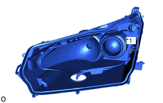
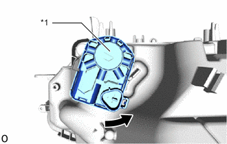
*1 Rail Align the headlight unit assembly LH with the rail and set the headlight unit assembly LH onto the horizontal aiming screw.
-
While holding the headlight unit assembly LH with one hand so that it does not fall over, tighten the horizontal aiming screw 20 rotations until the headlight unit assembly LH is connected.
-
Attach the pivot collar.
-
Tighten the horizontal aiming screw until the protrusion amount is the same as that recorded.
-
-
INSTALL HEADLIGHT LENS GASKET
-

Area to Clean Clean the headlight lens gasket installation groove.
-
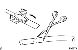
Prepare 2 screwdrivers, fold a piece of peeling paper over the tip of each screwdriver and fix the piecesof peeling paper in place with tape.
Tech Tips
Use the peeling paper that is supplied with the headlight lens gasket.
-
Using scissors, cut the end of the headlight lens gasket at a diagonal (45°).
-
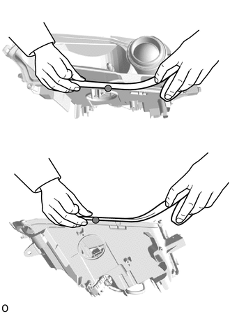

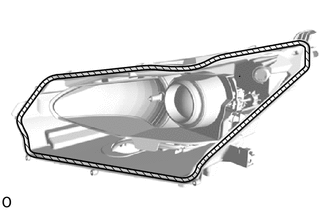
Starting Point Starting at the center headlight lens LH screw installation point, set the headlight lens gasket into the straight groove counterclockwise until it meets the corner groove.
Note
Lightly set the gasket in place without pulling.
-
Using 2 screwdrivers with their tips wrapped with peeling paper, push the headlight lens gasket into the bottom of the groove.
-
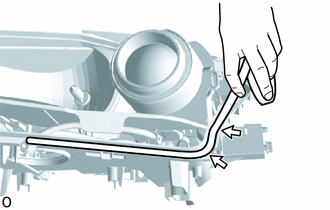

Corner Groove Set the headlight lens gasket into the corner groove and using 2 screwdrivers with their tips wrapped with peeling paper, push the gasket into the bottom of the groove.
Note
-
Lightly set the gasket in place without pulling.
-
If the headlight lens gasket is set while pulled, the gasket will be pushed up at the corner groove.
-
-

Push In Peeling Paper Repeat the following order while working in a circle back to the starting point: 1) Set headlight lens gasket into straight groove, 2) push into bottom of groove, 3) set into the corner groove and 4) push into bottom of groove.
-
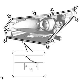
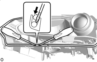
*a 10 mm (0.3937 in.) Corner Groove Using scissors, cut the headlight lens gasket at a 45° angle at the starting point so that the gasket overlaps itself 10 mm (0.3937 in.) or more and set the gasket in place.
-
Check the installation condition of the headlight lens gasket.
OK Gasket not pushed up or protruding. No gap where gasket overlaps. Note
Check the corners carefully since the gasket can easily become pushed up in those areas.
-
-
INSTALL HEADLIGHT LENS LH
Note
-
Perform work using rubber gloves.
-
Do not touch the headlight lens LH with bare hands.
-
If dirty, lightly wipe with a soft cloth.
-
Clean the headlight lens gasket contact surface.
-
Set the headlight lens LH in place.
-
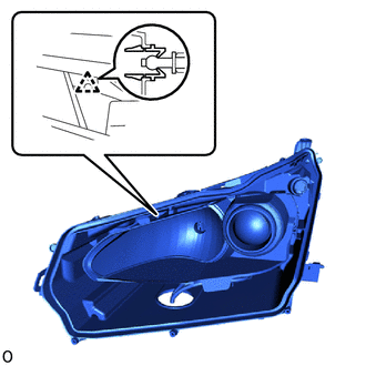
Attach the 8 claws.
Tech Tips
Attach the claw at the base point first.
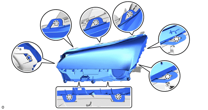
*a Base Point - - -
Using a T20H "TORX" screwdriver, install the 3 screws.
-
Install the 3 screws.
-
Check the condition of the headlight lens gasket.
OK Gasket contacts headlight lens LH and does not protrude out.
-
-
INSTALL HEADLIGHT LEVELING MOTOR BASE PACKING
-
Install a new headlight leveling motor base packing.
-
-
INSTALL HEADLIGHT LEVELING MOTOR LH
-
Set the tip of the aiming screw of the headlight leveling motor LH onto the headlight unit assembly LH.
-
Tighten the aiming screw of the headlight leveling motor LH the same number of rotations recorded when removing it to connect the headlight leveling motor LH.
-
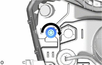
*1 Aiming Screw Counterclockwise Insert the headlight leveling motor LH.
-
Turn the headlight leveling motor LH counterclockwise to install it.
Tech Tips
For the headlight assembly RH, turn the headlight leveling motor RH clockwise to install it.
-
Tighten the aiming screw 20 rotations.
-
Connect the connector.
-
-
INSTALL HEADLIGHT GASKET
-
INSTALL HEADLIGHT LIGHT CONTROL ECU SUB-ASSEMBLY LH
-
INSTALL NO. 1 HEADLIGHT BULB
-
Connect the connector.
Note
Do not touch the bulb glass with bare hands.
-
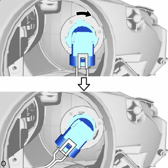
Clockwise Set and turn the No. 1 headlight bulb clockwise to install it.
-
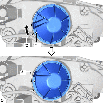
*1 Matchmark *2 Unlock Position Mark *3 Lock Position Mark Clockwise Align the matchmark of the headlight bulb cover to the unlock position mark, and then rotate the headlight bulb cover clockwise until the lock position mark to install the headlight bulb cover.
-